Temporally dispersed modulation method

a modulation method and temporal dispersion technology, applied in the field of pulse width modulation techniques in driving pixel cells, can solve the problems of affecting the display, the most difficult control of contouring (dfc), and the unique set of problems of image display implemented with pulse width modulation techniques, so as to reduce visual disruption

Inactive Publication Date: 2005-03-24
JASPER DISPLAY
View PDF6 Cites 32 Cited by
  • Summary
  • Abstract
  • Description
  • Claims
  • Application Information

AI Technical Summary

Benefits of technology

[0019] It is therefore an object of the present invention is to provide a novel system and method for reducing the visual disruption created by possi...

Problems solved by technology

Recent developments of image display implemented with the pulse width modulation (PWM) techniques are confronted with a unique set of problems caused by the artifacts generated due to the application of PWM in addition to the common display elements.
Particularly, the artifacts generated due to the dynamic false contouring (DFC) is an artifact that is most difficult to control.
For example, flicker was deemed unacceptable during the introduction of television receivers in the 1940s when the original NTSC television system was deployed in the United States.
As will be further discussed below, the conventional width modulation (PWM) techniques are still confronted with the problems of DFC when PMW is applied.
The dynamic false contours are distracting to all observers and as a result have been the subject of significant research on the part of companies seeking to ship commercial products that use pulse w...

Method used


Image

  • Temporally dispersed modulation method
  • Temporally dispersed modulation method
  • Temporally dispersed modulation method

Examples


Embodiment Construction

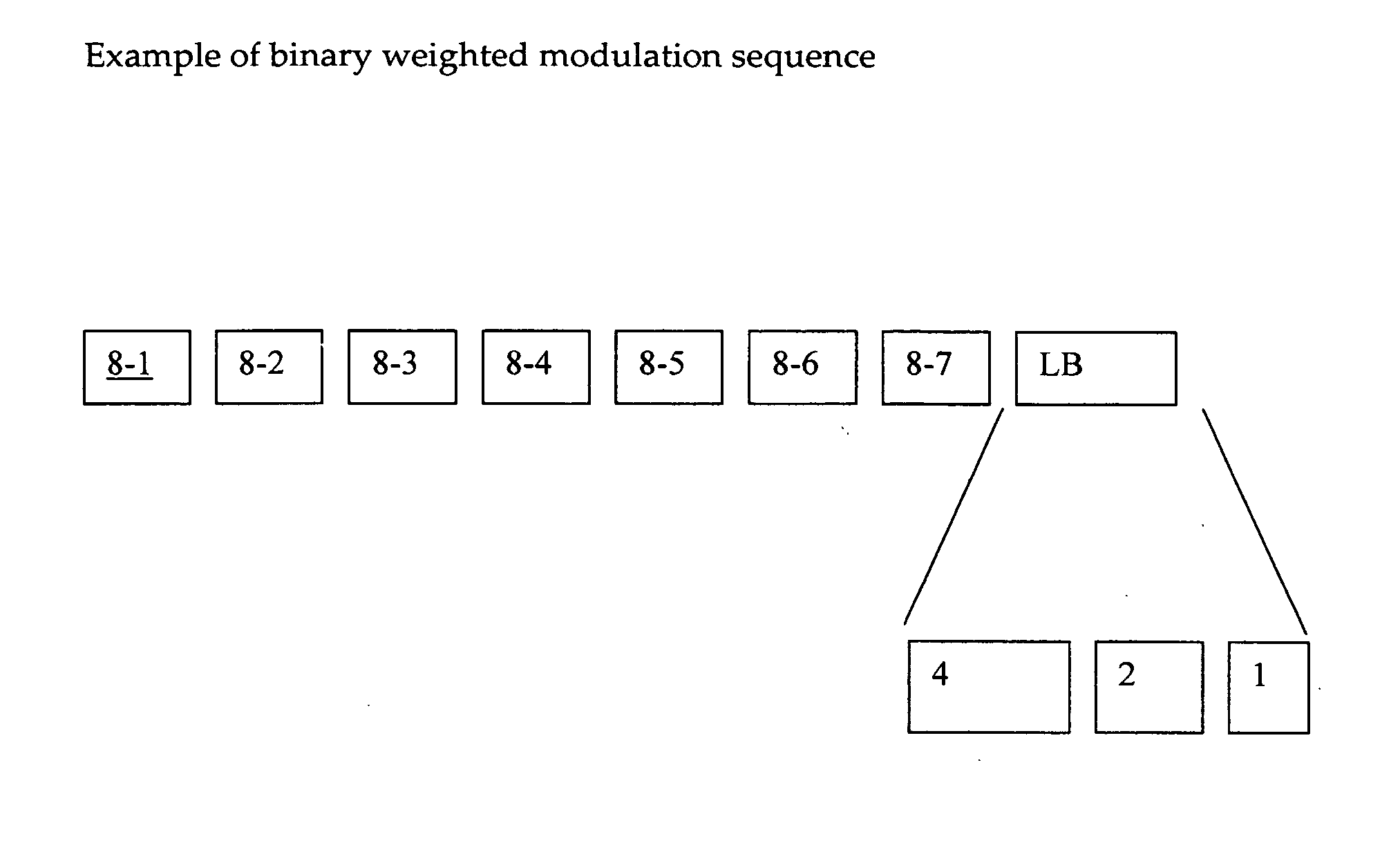
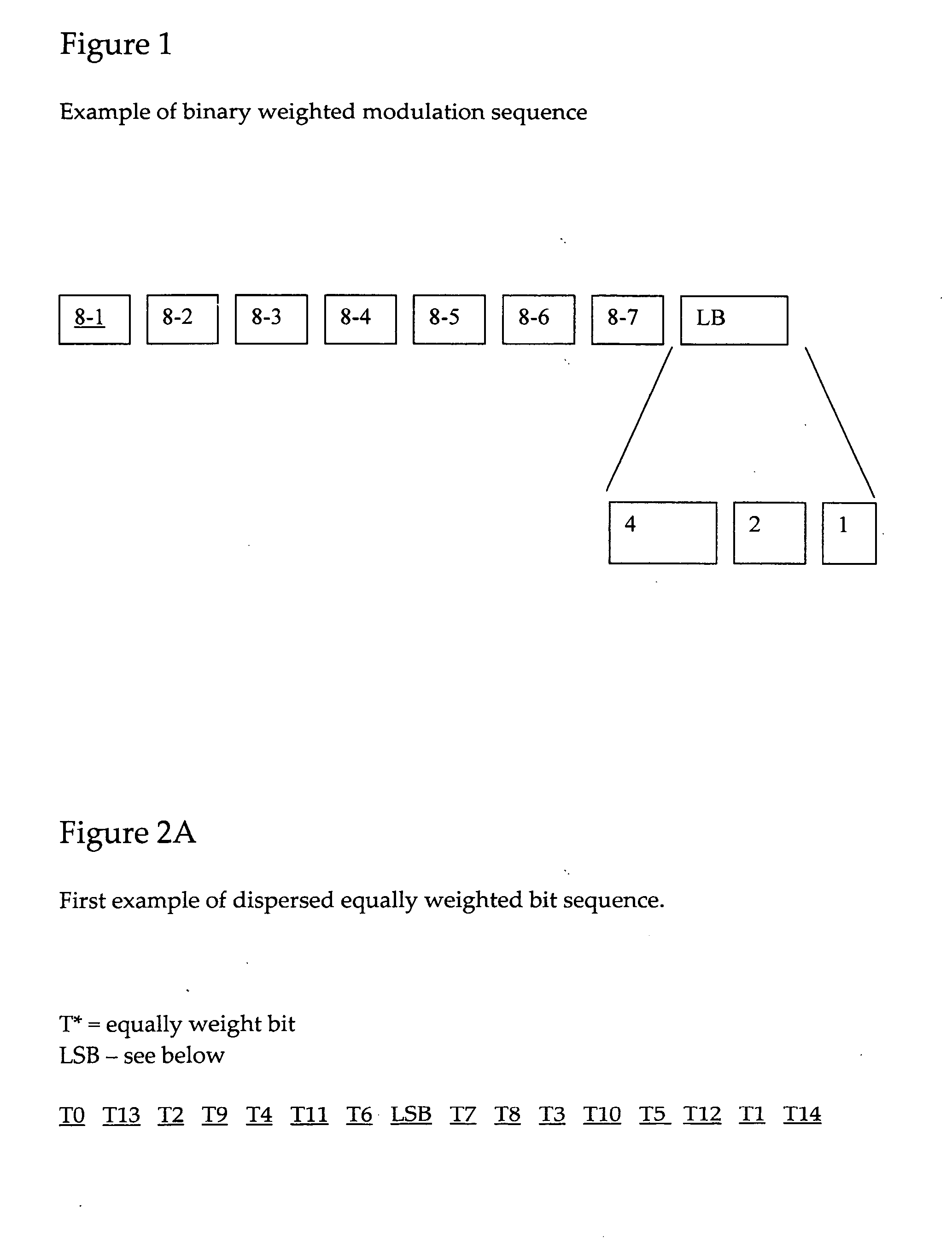
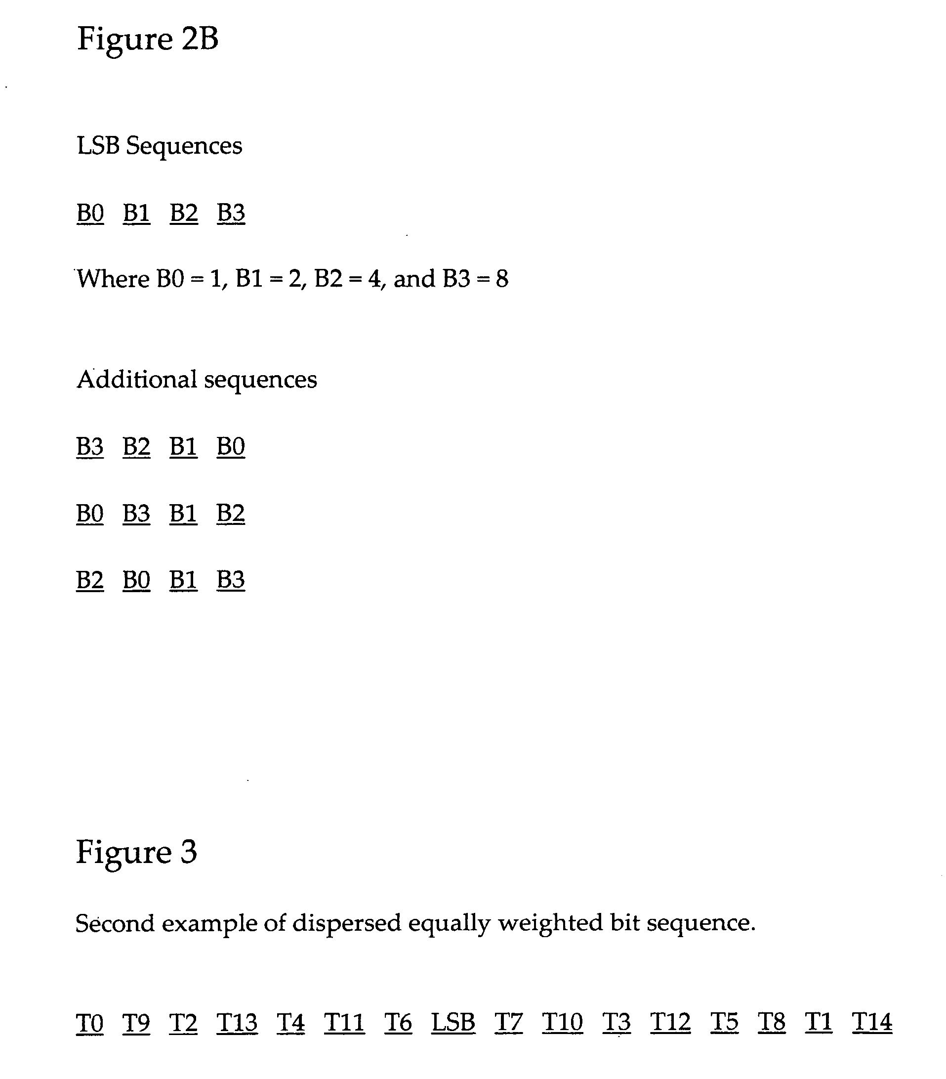
[0027] The present invention addresses the foregoing problems in a unique and novel fashion. Special considerations are paid to the visual disruptions between adjacent pixels in order to reduce the number of temporal artifacts observed by modifying the order in which equally weighted data bits are shown. Unlike the methods used by the U.S. Pat. Nos. 6,151,011 and 6,326,380 wherein the binary weighted data words are converted into equally weighted words and asserting to the pixel circuit by ordering them in ascending or descending order. The sequence of the equally weighted bits as disclosed in the present invention are dispersed to create at least two temporal “on” centers as gray scale increases and a higher number of equally weighted bits are required.

[0028] Additionally the cluster of lesser binary-weighted bits is now moved to a position near the temporal center of the sequence. While it could remain at one end or the other, the relocation of the lesser binary-weighted bits to ...


PUM


Abstract

A display system includes a controller for carrying out a data bit modulation sequence for driving a display pixel. The controller applies a plurality of sets of data bits for representing a data word and temporarily dispersing the sets for sequentially writing to the display pixel whereby the display pixel displaying a temporarily dispersed intensity. The display system may be wide varieties of display systems including but not limited to a liquid crystal on silicon display, a digital micromirror display, a plasma panel display, or a direct view liquid crystal device.

Description

[0001] This Application claims a Priority Date of Sep. 23, 2003, benefited from a previously filed Provisional Applications 60 / 505,194 filed on Sep. 23, 2003 by one of a common Applicant of this Patent Application.BACKGROUND OF THE INVENTION [0002] 1. Field of the Invention [0003] The present invention pertains to image display systems. More particularly, this invention relates to an improved pulse width modulation technique in driving a pixel cell by temporarily dispersed modulation for reducing visual disruptions between adjacent pixels caused by transverse electrical fields applied to adjacent electrodes due to phase differences of weighted data bits asserted to adjacent pixels. [0004] 2. Description of the Prior Art [0005] Recent developments of image display implemented with the pulse width modulation (PWM) techniques are confronted with a unique set of problems caused by the artifacts generated due to the application of PWM in addition to the common display elements. Particula...

Claims


Application Information

Patent Timeline
IPC IPC(8): G09G3/20G09G5/10
CPCG09G2320/0266G09G3/2022
Inventor HUDSON, EDWIN LYLE
Owner JASPER DISPLAY
Why Eureka
Try Eureka