Radiographic apparatus and radiation detection signal processing method

a radiation detection and signal processing technology, applied in the field of radiographic equipment, can solve the problems of time lags whose adverse influence appears in x-ray images, blurred dynamic images, and inability to avoid artifacts, and achieve the effect of accurate elimination of time lags

Inactive Publication Date: 2005-03-24
SHIMADZU CORP
View PDF12 Cites 2 Cited by
  • Summary
  • Abstract
  • Description
  • Claims
  • Application Information

AI Technical Summary

Benefits of technology

This invention has been made having regard to the state of the art noted above, and its object is to provide a radiographic apparatus and a radiation detection signal processing method for accurately eliminating time lags, due to a radiation detecting device, of radiation detection signals taken from the radiation detecting device.
In this case, since the impulse response has a plurality of exponential functions, the impulse response becomes more accurate. In addition, since the relationship of correspondence between intensities of the exponential function as impulse response coefficients and radiation doses is stored for each of the exponential functions, the intensity of each exponential function may be set with increased accuracy. As a result, the lag-behind part may be removed properly from each radiation detection signal.
In this case, the relationship of correspondence between intensities of the exponential function and radiation doses may easily be stored in the form of the concise functional expression “αn=Q·logW+q”.
This radiation detection signal processing method allows the radiographic apparatus according to the invention to be implemented in an advantageous manner.

Problems solved by technology

However, the FPD has a drawback of causing time lags whose adverse influence appears in X-ray images.
This results in an inconvenience such as blurring of dynamic images.
However, the only result obtained is that the above technique cannot avoid artifacts due to the time lag and satisfactory X-ray images cannot be obtained.
It has been found, however, that it is impossible for one exponential function to approximate the time lag of the FPD, and the time lag is not eliminated by this technique, either.

Method used


Image

  • Radiographic apparatus and radiation detection signal processing method
  • Radiographic apparatus and radiation detection signal processing method
  • Radiographic apparatus and radiation detection signal processing method

Examples


first embodiment

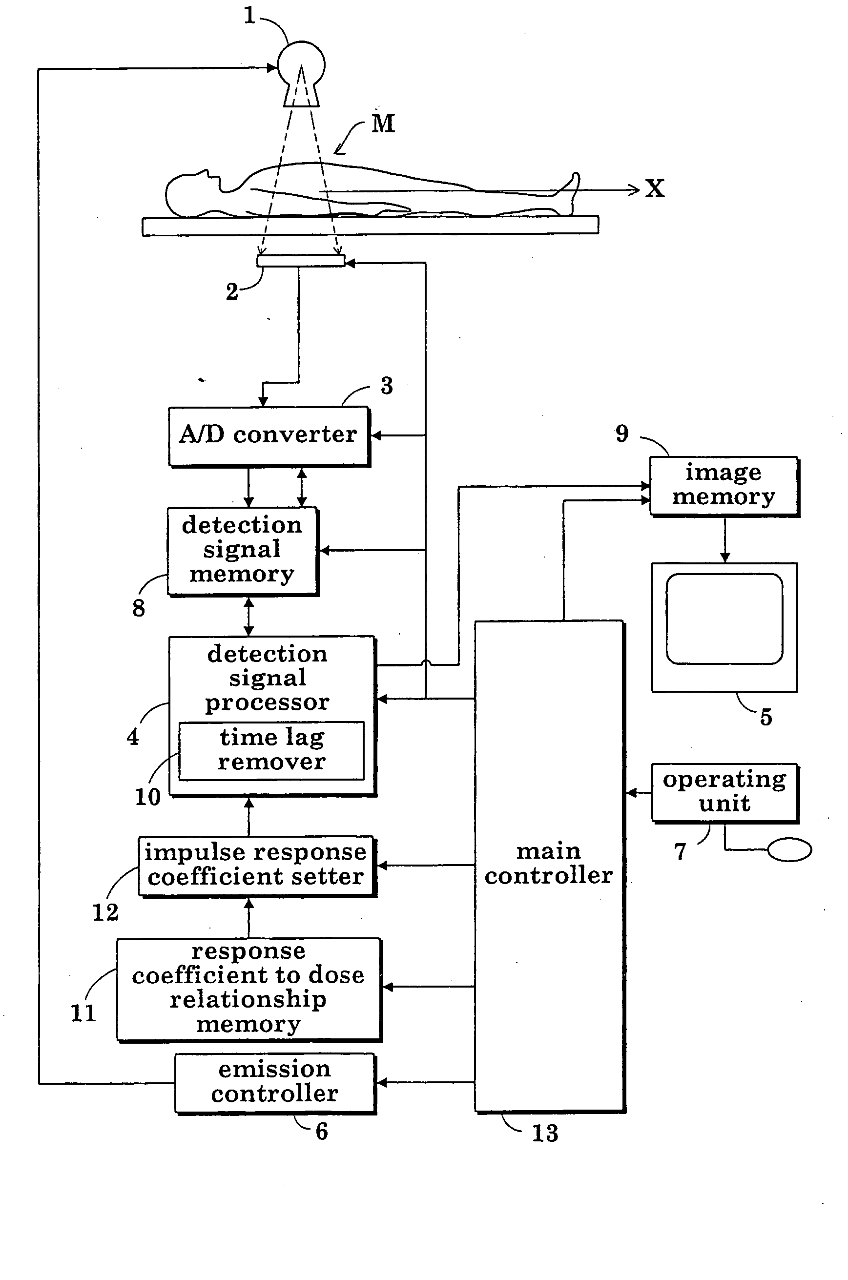
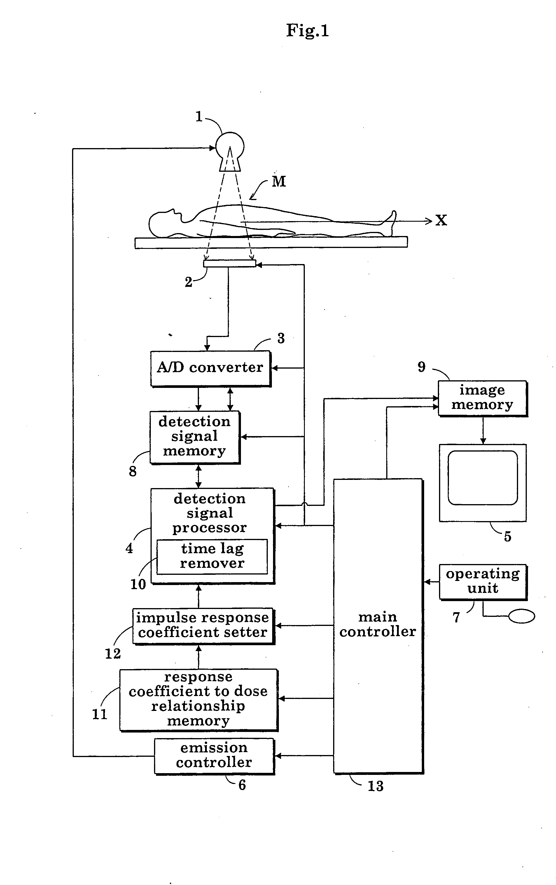
FIG. 1 is a block diagram showing an overall construction of a fluoroscopic apparatus in a first embodiment of this invention.

As shown in FIG. 1, the fluoroscopic apparatus includes an X-ray tube (radiation emitting device) 1 for emitting X rays toward a patient M, an FPD (radiation detecting device) 2 for detecting X rays transmitted through the patient M, an analog-to-digital converter 3 (signal sampling device) for digitizing X-ray detection signals (radiation detection signals) taken from the FPD (flat panel X-ray detector) 2 at predetermined sampling time intervals Δt, a detection signal processor 4 for creating X-ray images based on X-ray detection signals outputted from the analog-to-digital converter 3, and an image monitor 5 for displaying the X-ray images created by the detection signal processor 4. That is, the apparatus is constructed to acquire X-ray images from the X-ray detection signals taken from the FPD 2 by the analog-to-digital converter 3 as the patient M is i...

second embodiment

In the fluoroscopic apparatus in the second embodiment, the response coefficient to dose relationship memory 11 is a table memory for storing the relationship of correspondence between intensity an of the exponential function as impulse response coefficient and X-ray dose W not in the form of the functional expression but in table form. The other aspects of the apparatus are the same as in the first embodiment, and will not be described again.

In the apparatus in the second embodiment, the table memory stores the relationship of correspondence between intensity αn of the exponential function as impulse response coefficient and X-ray dose W in table form as shown in FIG. 10. The impulse response coefficient setter 12 checks an X-ray dose inputted by the operator against the table stored in the response coefficient to dose relationship memory 11, and reads and sets intensity an of the exponential function corresponding to the X-ray dose inputted by the operator.

With the apparatus ...


PUM

PropertyMeasurementUnit
attenuation time constantsaaaaaaaaaa
time constantsaaaaaaaaaa
processingaaaaaaaaaa

Abstract

An apparatus according to the invention includes a response coefficient to dose relationship memory for storing, in advance, a relationship of correspondence between intensities of an exponential function for impulse response and X-ray doses. The intensities of the exponential function determine conditions relating to an impulse response in a recursive computation performed to remove lag-behind parts from X-ray detection signals outputted from an FPD, thereby to obtain corrected X-ray detection signals. An impulse response coefficient setter sets an impulse response coefficient corresponding to an X-ray dose for an object under examination based on the relationship of correspondence between intensities of the exponential function and radiation doses. A time lag remover performs the recursive computation for time lag removal, with the intensity of an exponential function set to correspond to the X-ray dose for the object under examination. Thus, a lag-behind part is removed properly from each X-ray detection signal.

Description

BACKGROUND OF THE INVENTION (1) Field of the Invention This invention relates to a radiographic apparatus for medical or industrial use and a radiation detection signal processing method, for obtaining radiographic images based on radiation detection signals fetched at predetermined sampling time intervals by a signal sampling device from a radiation detecting device as radiation is emitted from a radiation emitting device. More particularly, the invention relates to a technique for eliminating time lags, due to the radiation detecting device, of the radiation detection signals taken from the radiation detecting device. (2) Description of the Related Art In a medical fluoroscopic apparatus which is a typical example of radiographic apparatus, a flat panel X-ray detector (hereinafter called “FPD” as appropriate) has recently been used as an X-ray detecting device for detecting X-ray penetration images of a patient resulting from X-ray emission from an X-ray tube. The FPD includes...

Claims


Application Information

Patent Timeline
Patent Type & Authority Applications(United States)
IPC IPC(8): G01T1/17A61B6/00A61B6/02G01N23/04G01T1/20G01T1/24G03B42/02H04N5/225H04N5/232
CPCA61B6/4225A61B6/542G01N2223/612G01N2223/419G01N23/046A61B6/00
Inventor OKAMURA, SHOICHI
Owner SHIMADZU CORP
Why Eureka
Try Eureka