Tangential cutting insert and milling cutter

a technology of cutting inserts and milling cutters, which is applied in the direction of shaping cutters, turning machine accessories, manufacturing tools, etc., can solve the problems of negative axial rake angles, limited axial rake angle of inserts, and increased “vertical” exten

Inactive Publication Date: 2005-03-24
ISCAR LTD
View PDF16 Cites 60 Cited by
  • Summary
  • Abstract
  • Description
  • Claims
  • Application Information

AI Technical Summary

Benefits of technology

[0019] In accordance with the present invention, the given axial abutment region is located on a forward region of a radi...

Problems solved by technology

However, negative axial rake angles are disadvantageous, e.g., they have been found to be deficient in cutting applications involving difficult-to-machine materials.
It will be appreciated that the magnitude of the insert axial rake angle is limited for practical reasons.
Any increase in the insert axial rake angle will result in an increase in the ...

Method used


Image

  • Tangential cutting insert and milling cutter
  • Tangential cutting insert and milling cutter
  • Tangential cutting insert and milling cutter

Examples


Embodiment Construction

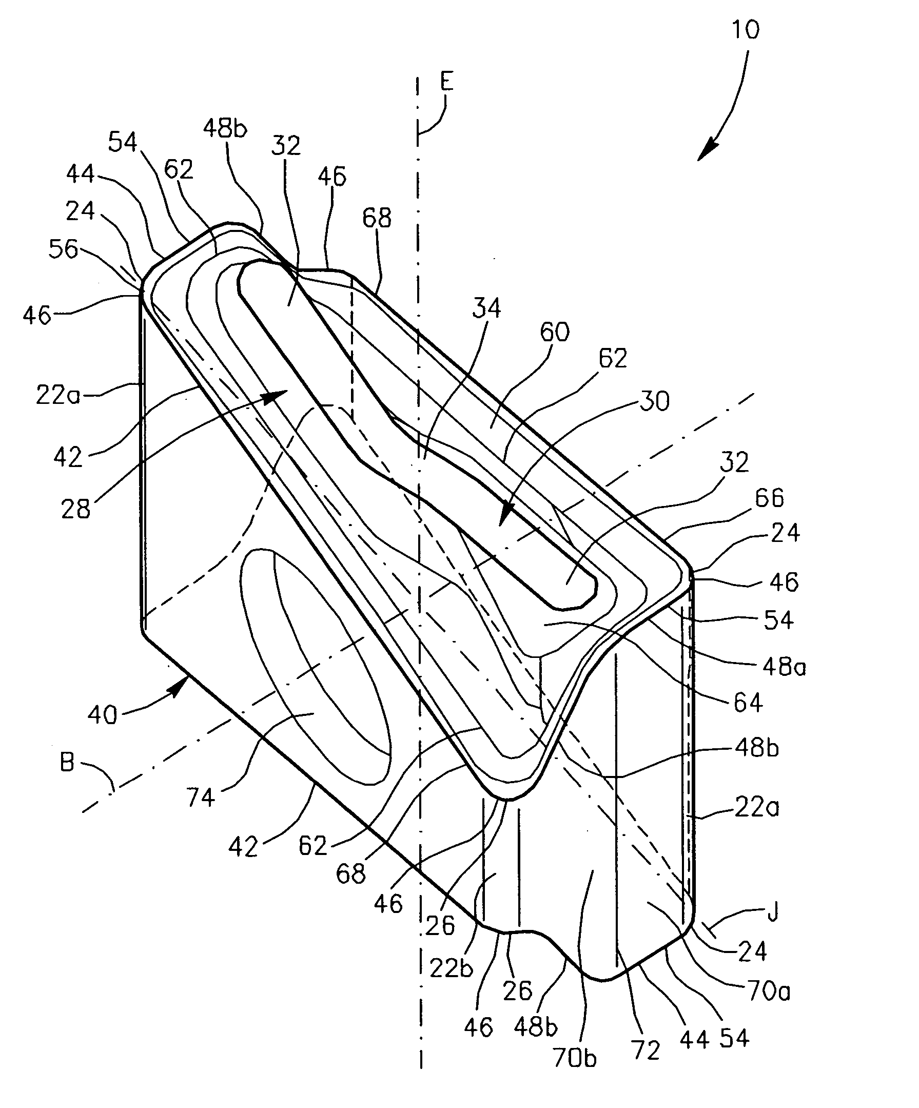
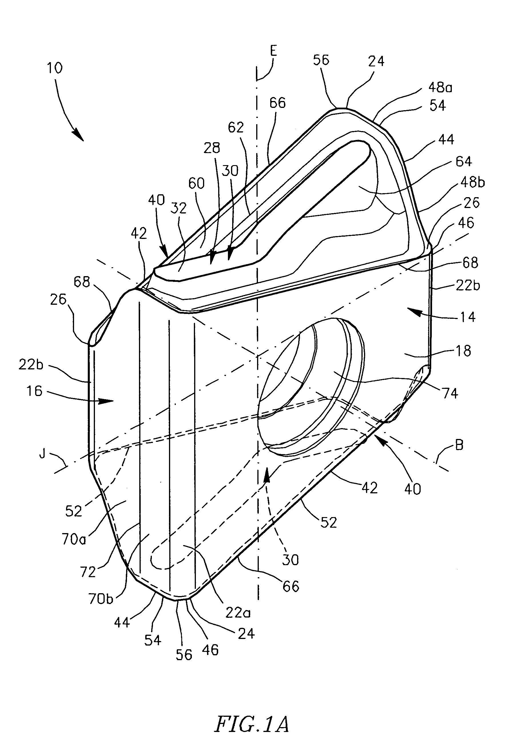
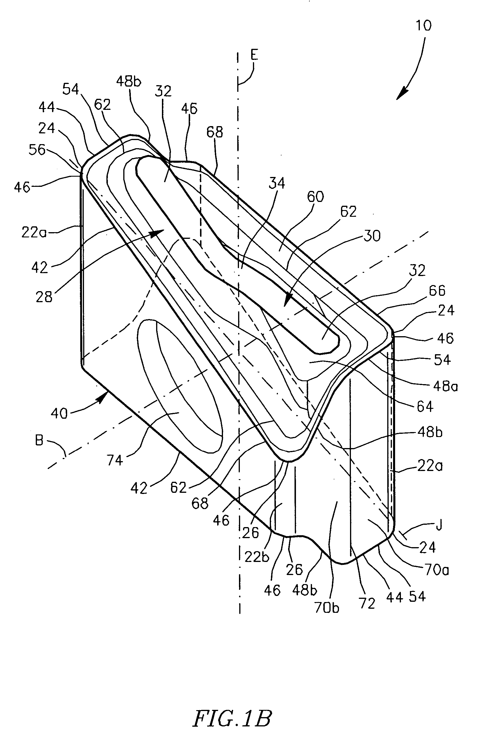
[0040] Attention is first drawn to FIGS. 1 to 5, showing an indexable tangential cutting insert 10 in accordance with a first embodiment of the present invention. The cutting insert 10 is typically manufactured by form-pressing and sintering carbide powders. However, other manufacturing methods, such as injection molding, can be used. The cutting insert 10 is generally rectangular in an end view and has two identical opposing end surfaces 12. Each end surface 12 has 180° rotational symmetry about an axis of symmetry E passing through the two end surfaces 12. The cutting insert 10 is mirror symmetric with respect to a median plane M of the cutting insert 10. The median plane M is perpendicular to the axis of symmetry E and passes between the end surfaces 12.

[0041] A peripheral side surface 14 extends between the two opposing end surfaces 12 and comprises two opposed identical minor side surfaces 16, two opposed identical major side surfaces 18, two diagonally opposite long corner si...


PUM

PropertyMeasurementUnit
Lengthaaaaaaaaaa
Shapeaaaaaaaaaa

Abstract

A tangential milling cutting insert having two identical opposing end surfaces with two identical opposing major side surfaces of a generally isosceles trapezoidal shape and two identical opposing minor side surfaces extending between them is disclosed. Each end surface has a peripheral edge containing cutting edges and four corners of which two diagonally opposed corners are lowered and the other two are raised. Each end surface is provided with an abutment member having an abutment surface. In each cross section of the cutting insert taken in a plane parallel to a minor plane of the cutting insert, the abutment surface is closer to a median plane than a respective leading section of a major cutting edge.

Description

FIELD OF THE INVENTION [0001] The present invention relates to a tangential indexable cutting insert and a milling cutter for use in metal cutting processes in general and for milling a square shoulder in a workpiece in particular. BACKGROUND OF THE INVENTION [0002] Tangential cutting inserts, also known as on-edge, or lay down, cutting inserts, are oriented in an insert holder in such a manner that during a cutting operation on a workpiece the cutting forces are directed along a major (thicker) dimension of the cutting insert. An advantage of such an arrangement being that the cutting insert can withstand greater cutting forces than when oriented in such a manner that the cutting forces are directed along a minor (thinner) dimension of the cutting insert. [0003] There is disclosed in EP 0 769 341 a face milling cutter employing a double-sided indexable tangential cutting insert having a prismoidal shape with two opposed generally rectangular rake surfaces connected by side surfaces...

Claims


Application Information

Patent Timeline
IPC IPC(8): B23C5/10B23C5/22
CPCB23C5/1072B23C5/2213B23C2200/0472B23C2200/085B23C2200/205Y10T407/23B23C2200/367B23C2210/168Y10T407/1962Y10T407/1924B23C2200/286B23C2200/287
Inventor SATRAN, AMIR
Owner ISCAR LTD
Why Eureka
Try Eureka