Fuel cell flow field plate

a flow field plate and fuel cell technology, applied in the field of fuel cells, can solve the problems of significant affecting the performance of the fuel cell, unfavorable gas distribution along the tortuous flow path, and design problems, so as to facilitate gas distribution, reduce pressure drop, and prevent the accumulation of water and impurities.

Inactive Publication Date: 2005-03-24
HYDROGENICS CORP
View PDF29 Cites 13 Cited by
  • Summary
  • Abstract
  • Description
  • Claims
  • Application Information

AI Technical Summary

Benefits of technology

[0021] The design of the fuel cell flow field plate in accordance with the present invention provides more uniform gas distribution and reduced pressure drop across the flow field. The substantially straight flow channels prevent building-up of water and impurities. The MEA and GDM in the present invention are subject to less, if any, shearing effects resulting from offset of ribs in flow fields. The gas distribution is also facilitated, thereby resulting in improved fuel cell efficiency and enhanced power density. Moreover, feeding of reactant gases from rear face of the flow field plates provides a possibility for simplified sealing between flow field plates, reducing the risk of mixing reactant gases. In addition, the matching design of flow field ribs makes it possible to use narrower ribs and wider flow channels in the flow field. Hence, more GDM and MEA are exposed directly to reactant gases. Consequently, a larger portion of the active area of MEA can be utilized. This further improves the fuel cell efficiency. All theses advantages contribute to a fuel cell with better performance and easier maintenance.

Problems solved by technology

However, these designs suffer from a number of problems.
This is a serious problem that significantly affects the performance of the fuel cell when the fuel cell is operating under a relatively low pressure, for example, ambient pressure.
The gas distribution in these designs is also not uniform along the tortuous flow paths.
The gas flow is more turbulent in the serpentine flow field, making it more difficult to control the flow, pressure or temperature of the reactant gases.
In addition, tortuous flow paths provide more places for water or contaminants to accumulate in the channels, increasing the risk of flooding or poisoning the fuel cell.
Another problem associated with most of flow field designs is the ribs and channels on the anode flow field plate often offset with those on the cathode flow field plates when placed in a fuel cell stack.
Since pressure is often applied on a fuel cell stack, the MEA and GDM are thus subject to shearing force, which may eventually damage the MEA.
The offset of the ribs also impedes the distribution of reactant gases across GDM, reducing the fuel cell efficiency.
It can be appreciated from the previous discussion that a further problem in conventional fuel cell is that the sealing is often complicated.
In addition, as mentioned, a seal is required between each pair of adjacent plates and each seal would be of complex and elaborate construction.
In this configuration, part of the membrane would lie over open channels on the first flow field plate, and hence not be properly supported, thereby running the risk of there being inadequate sealing, resulting in a mixing of gases, which is highly undesirable.

Method used


Image

  • Fuel cell flow field plate
  • Fuel cell flow field plate
  • Fuel cell flow field plate

Examples


Embodiment Construction

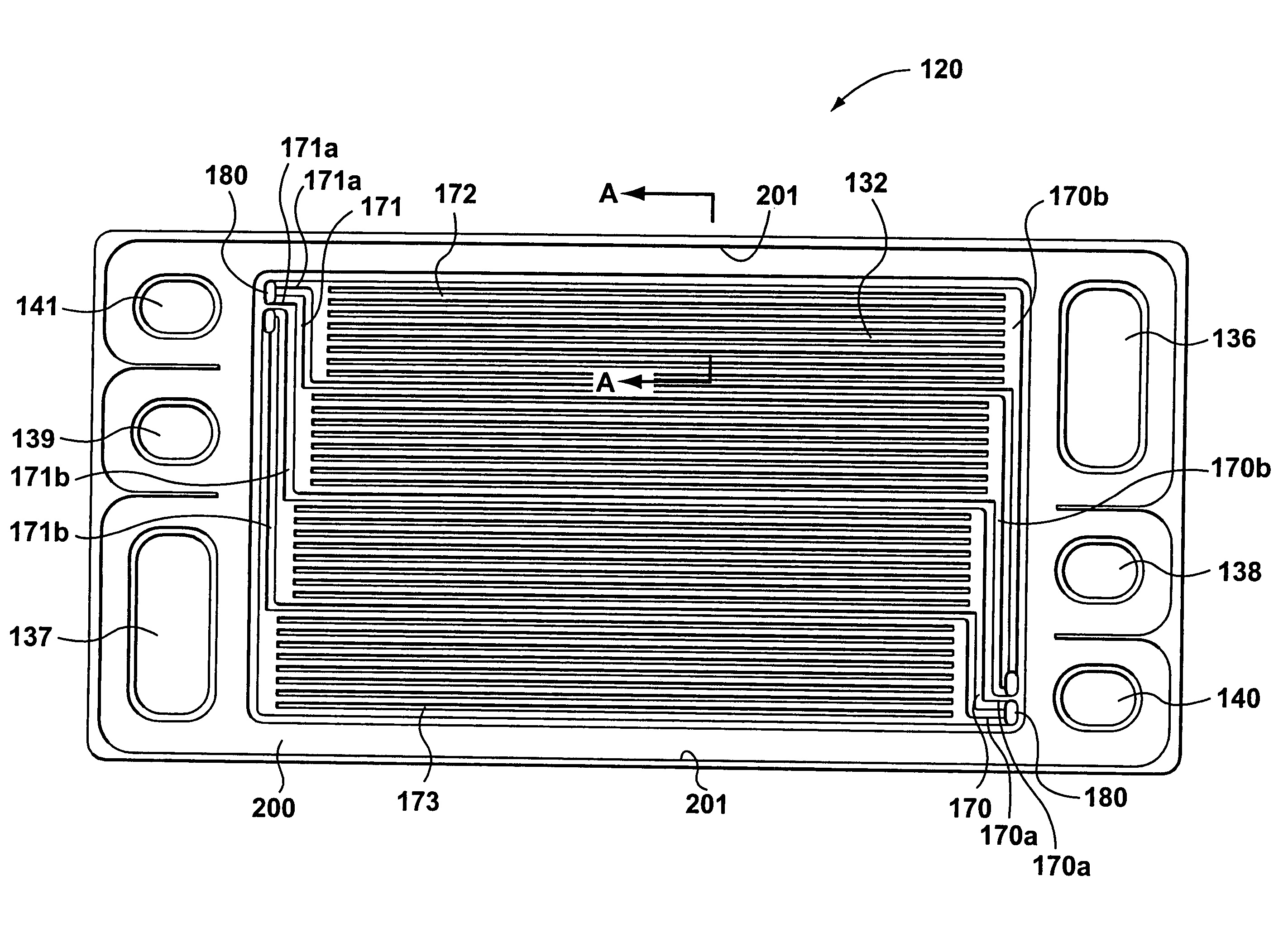
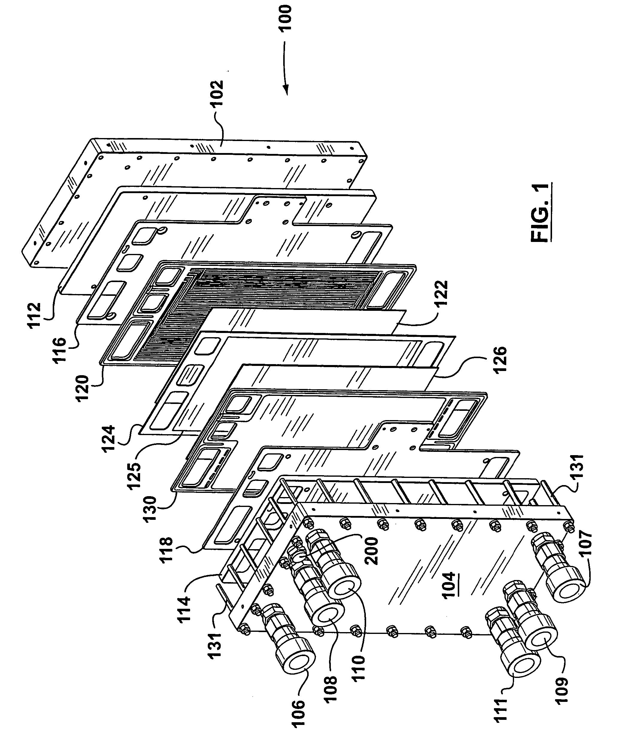
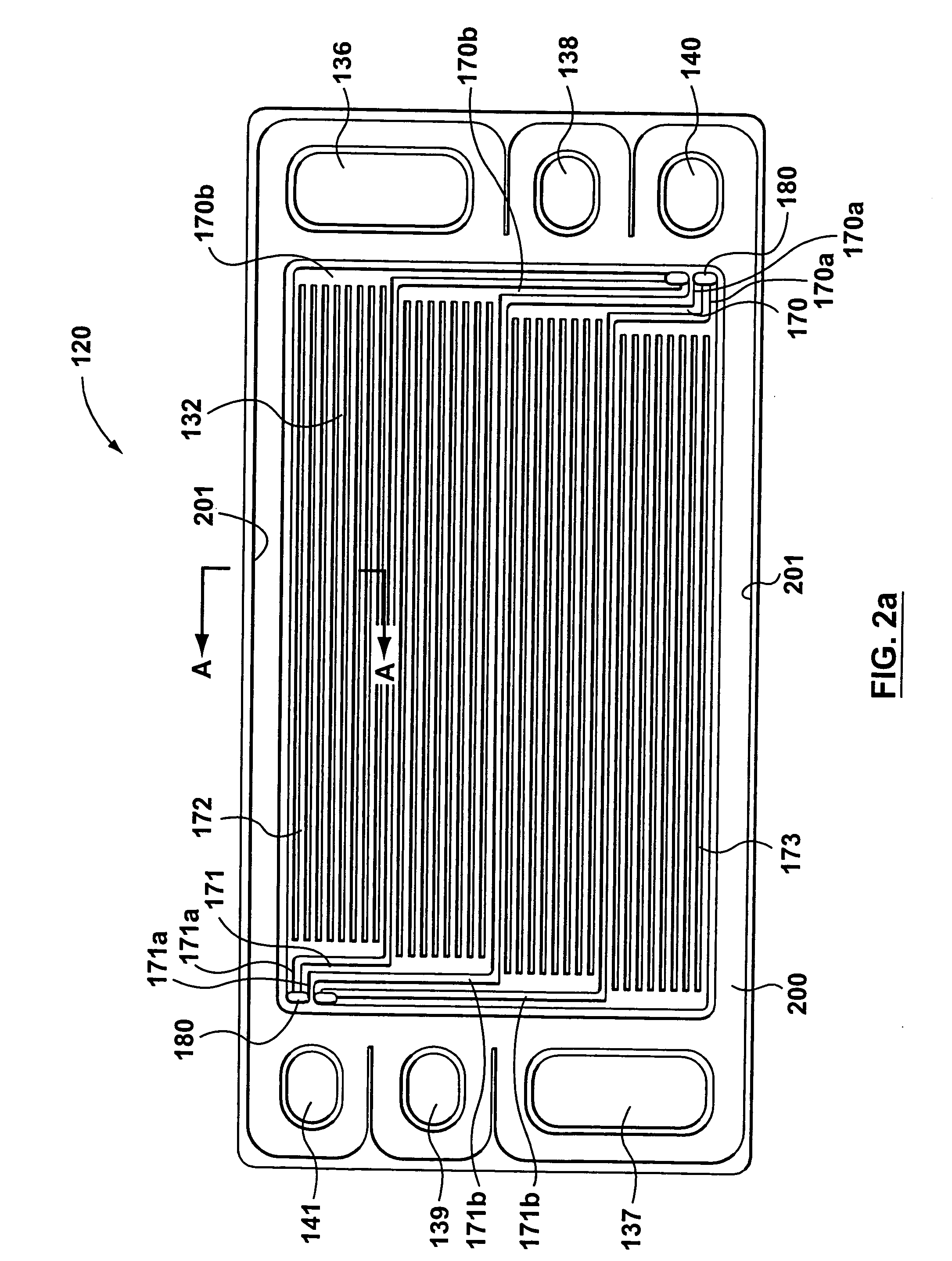
[0035] Referring first to FIG. 1, this shows an exploded perspective view of a single fuel cell unit 100 located within a fuel cell stack according to the present invention. It is to be understood that while a single fuel cell unit 100 is detailed below, in known manner the fuel cell stack will usually comprise a plurality of fuel cells stacked together. Each fuel cell of the fuel cell unit 100 comprises an anode flow field plate 120, a cathode flow field plate 130, and a membrane electrode assembly (MEA) 124 disposed between the anode and cathode flow field plates 120, 130. Each reactant flow field plate has an inlet region, an outlet region, and open-faced channels to fluidly connect the inlet to the outlet, and provide a way for distributing the reactant gases to the outer surfaces of the MEA 124. The MEA 124 comprises a solid electrolyte (i.e. a proton exchange membrane) 125 disposed between an anode catalyst layer (not shown) and a cathode catalyst layer (not shown). A first ga...


PUM

PropertyMeasurementUnit
radiusaaaaaaaaaa
radiusaaaaaaaaaa
radiusaaaaaaaaaa

Abstract

A fuel cell stack comprising a plurality of fuel cells, each having an anode flow field plate, a cathode flow field plate and a membrane electrode assembly disposed between the flow field plates. The anode and cathode flow field plates have primary channels and ribs separating the primary channels. At least a portion of the anode and cathode primary channels are disposed directly opposite one another with a membrane exchange assembly therebetween and with at least some of the ribs on the anode and cathode flow field plates located directly opposite one another to sandwich the membrane exchange assembly therebetween. The flow field plates can also have inlet distribution and outlet collection channels. Each of these distribution and collection channels is connected to a plurality of the primary channels, preferably located centrally, so as to improve flow distribution of the reactants.

Description

RELATED APPLICATIONS [0001] This application is a divisional application of U.S. patent application Ser. No. 10 / 109,002, filed Mar. 29, 2002 which is a continuation in part of U.S. patent application Ser. No. 09 / 855,018, filed May 15, 2001.FIELD OF THE INVENTION [0002] The present invention relates to fuel cells. More particularly, the present invention relates to configuration of fuel cell flow field plates. BACKGROUND OF THE INVENTION [0003] Fuel cells have been proposed as a clean, efficient and environmentally friendly source of power which can be utilized for various applications. A fuel cell is an electrochemical device that produces an electromotive force by bringing the fuel (typically hydrogen) and an oxidant (typically air) into contact with two suitable electrodes and an electrolyte. A fuel, such as hydrogen gas, for example, is introduced at a first electrode, i.e. anode where it reacts electrochemically in the presence of the electrolyte to produce electrons and cations...

Claims


Application Information

Patent Timeline
Patent Type & Authority Applications(United States)
IPC IPC(8): H01M8/02H01M8/04H01M8/10H01M8/24
CPCH01M8/0228H01M8/0247H01M8/0258H01M8/026H01M8/0263H01M8/0267Y02E60/50H01M8/04089H01M8/1002H01M8/241H01M8/2415H01M8/242H01M8/248H01M8/0297H01M8/1007H01M8/2483H01M8/2457H01M8/2484
Inventor FRANK, DAVIDCHEN, XUESONGSORBERA, SONIAJOOS, NATHANIEL IAN
Owner HYDROGENICS CORP
Why Eureka
Try Eureka