
High quality and high performance three-dimensional graphics architecture for portable handheld devices

a portable handheld device, high-performance technology, applied in static indicating devices, liquid/fluent solid measurements, instruments, etc., can solve the problems of low performance components of portable handheld devices, over-all system energy consumption and cost, and the rendering of 3d objects can be extremely computation and power-intensive, and achieve high quality and high performance.

Active Publication Date: 2005-03-24
NVIDIA CORP
View PDF10 Cites 125 Cited by
  • Summary
  • Abstract
  • Description
  • Claims
  • Application Information

AI Technical Summary

Benefits of technology

Accordingly, the present invention provides a high quality and high performance 3D graphics architecture suitable for portable handheld devices where power consumption is a crucial consideration.

Problems solved by technology

These portable handheld devices face the challenge of providing a compelling user experience while reducing overall system energy consumption and cost.
Traditionally, portable handheld devices have lower-performance components than desktop Personal Computers (PCs) primarily because of the power limitations inherent in battery-operated handheld devices.
In general, the rendering of 3D objects can be extremely computation and power intensive and therefore is not conducive to battery-operated handheld devices.
As the number of triangles increases, the complexity and power consumption of the logic that performs these calculations also increases.
While the '089 patent may teach a video graphics circuit with improved performance, it does not address the issue of power conservation.
As a result, the graphics circuit of the '089 patent is not suitable for use in battery-operated portable handheld devices where power conservation is a crucial consideration.
Like the '089 patent, the '550 patent teaches a video graphics circuit with improved performance, it does not address the issue of power conservation.
As a result, the graphics circuit of the '550 patent is also not suitable for use in battery-operated portable handheld devices where power conservation is a crucial consideration.

Method used


Image

  • High quality and high performance three-dimensional graphics architecture for portable handheld devices
  • High quality and high performance three-dimensional graphics architecture for portable handheld devices
  • High quality and high performance three-dimensional graphics architecture for portable handheld devices

Examples


first embodiment

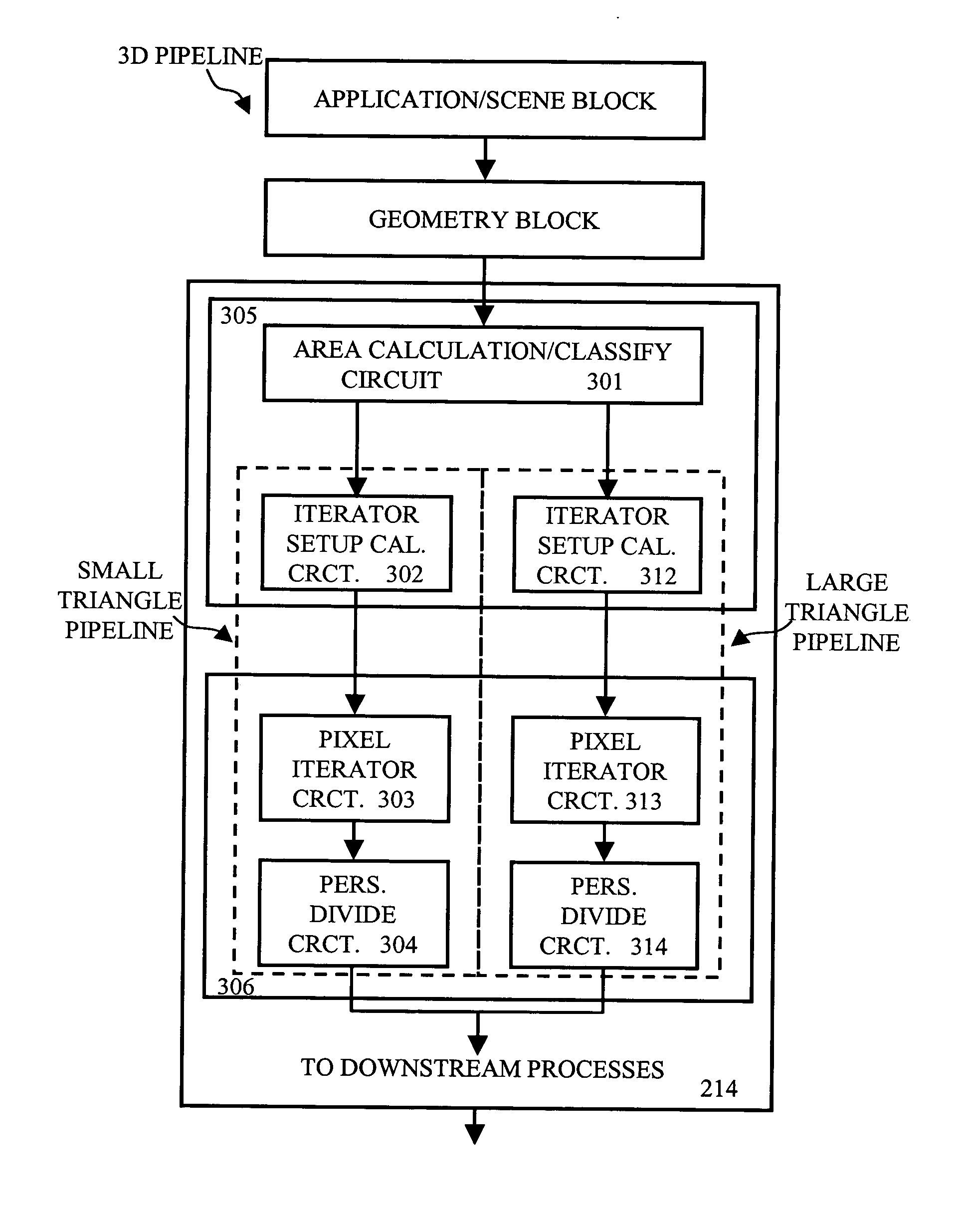
Referring now to FIG. 3 illustrating the relevant components of 3D GE 214 which implements the present invention. As shown in FIG. 3, 3D GE 214 includes area calculation / classify circuit 301, iterator setup calculation circuit 302, iterator setup calculation circuit 312, pixel iterator circuit 303, pixel iterator circuit 313, perspective divide circuit 304, and perspective divide circuit 314. Area calculation / classify circuit 301, iterator setup calculation circuit 302, and iterator setup calculation circuit 312 form triangle setup engine 305. Pixel iterator circuit 303, pixel iterator circuit 313, perspective divide circuit 304, and perspective divide circuit 314 form rasterizing / rendering engine 306. However, it should be noted that instead of being part of triangle setup engine 305 as shown in FIG. 3, iterator setup calculation circuit 302 and iterator setup calculation circuit 312 can also be made part of rasterizing / rendering engine 306 as shown by the broken-line box. As shown...

third embodiment

Referring now to FIG. 6 illustrating the relevant components of 3D GE 214 which implements the present invention. As shown in FIG. 6, 3D GE 214 includes area calculation / classify circuit 601, iterator setup calculation circuit 602, pixel iterator circuit 603, and perspective divide circuit 604. Iterator setup calculation circuit 602 can be configured dynamically to operate in a low-precision mode (e.g., when small and well-behaved triangles are involved) or in a high-precision mode (e.g., when large or misbehaved triangles are involved). More specifically, in a low-precision mode, iterator setup calculation circuit 602 disables (set to zero) one or more LSBs of the mantissa when processing of small and well-behaved triangles. Conversely, in a high-precision mode, iterator setup calculation circuit 602 uses the full width of the mantissa when processing large or misbehaved triangles. In this embodiment, after a triangle classification is determined, area calculation / classification ci...

fourth embodiment

Reference is now made to FIG. 8 which illustrates the relevant components of 3D GE 214 that implements the present invention. As shown in FIG. 8, 3D GE 214 includes area calculation / classify circuit 801, iterator setup calculation circuit 802, pixel iterator circuit 803, and perspective divide circuit 804. Additionally, the current embodiment further includes precision select circuit 815 which is connected to user interface 816 and / or power monitor 817. Precision select circuit 815 may be external of 3D GE 214 (as shown in FIG. 8) or internal of 3D GE 214. User interface 816 allows a user to manually select a desired power level and accordingly an associated precision mode. User interface 816 may be a Graphical User Interface (GUI), a command line interface, a touch screen interface, a voice-activated interface, a menu-driven interface, a manual switch, etc. Hence, using user interface 816, the user may select a low-power low-precision mode to maximize battery life, a high-power hig...


PUM


Abstract

A high quality and performance 3D graphics architecture suitable for portable handheld devices is provided. The 3D graphics architecture incorporates a module to classify polygons by size and other characteristics. In general, small and well-behaved triangles can be processed using “lower-precision” units with power efficient circuitry without any quality and performance sacrifice (e.g., realism, resolution, etc.). By classifying the primitives and selecting the more power-efficient processing unit to process the primitive, power consumption can be reduced without quality and performance sacrifice.

Description

FIELD OF THE INVENTION The invention generally relates to computer systems, and more particularly relates to computer graphics triangle setup and rasterization units designed to achieve optimal power savings. BACKGROUND OF THE INVENTION Battery-operated and portable handheld devices that perform real-time Three-Dimensional (3D) imaging such as Personal Digital Assistants (PDAs), cellular phones, and handheld electronic games have become enormously popular. Their popularity is fueled in part by the available network connectivity options. Wireless data services now enable a new generation of high-performance, low-power-consumption handheld devices to access network-centric applications and content anywhere, anytime. As a result, these handheld devices, in addition to having the capability to provide mobile phone services, are capable of supporting 2-way video, sharing pictures and video clips, providing a rich web experience, and more. As mobile applications become richer and more ...

Claims


Application Information

Patent Timeline
IPC IPC(8): G06F1/32G06F7/499G06TG06T15/00
CPCG06F1/3203G06F1/3293Y02B60/121G06T15/005G06F7/49942Y02D10/00G06T1/00
Inventor HOLMER, BRUCE
Owner NVIDIA CORP
Learn More