Liquefied natural gas processing
- Summary
- Abstract
- Description
- Claims
- Application Information
AI Technical Summary
Problems solved by technology
Method used
Image
Examples
example 1
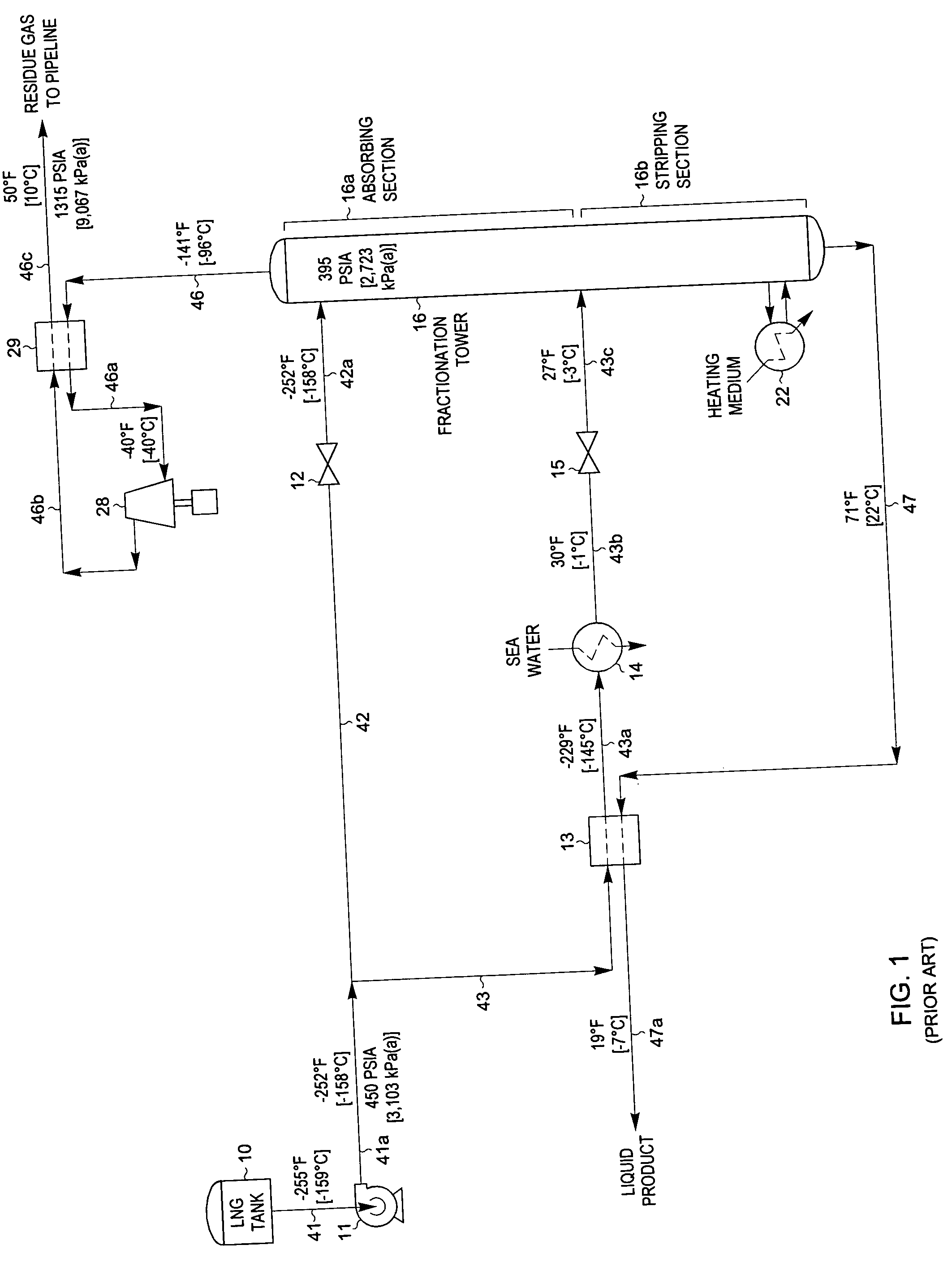
[0050]FIG. 10 illustrates a flow diagram of a process in accordance with the present invention. The LNG composition and conditions considered in the process presented in FIG. 10 are the same as those in FIGS. 1, 4, and 7. Accordingly, the FIG. 10 process can be compared with that of the FIGS. 1, 4, and 7 processes to illustrate the advantages of the present invention.
[0051] In the simulation of the FIG. 10 process, the LNG to be processed (stream 41) from LNG tank 10 enters pump 11 at −255° F. [−159° C.]. Pump 11 elevates the pressure of the LNG sufficiently so that it can flow through heat exchangers and thence to fractionation tower 16. Stream 41a exiting the pump is heated to −152° F. [−102° C.] in reflux condenser 17 as it provides cooling to the overhead vapor (stream 46) from fractionation tower 16. Stream 41b exiting reflux condenser 17 is split into two portions, streams 42 and 43. The first portion, stream 42, is expanded to the operating pressure (approximately 400 psia [...
example 2
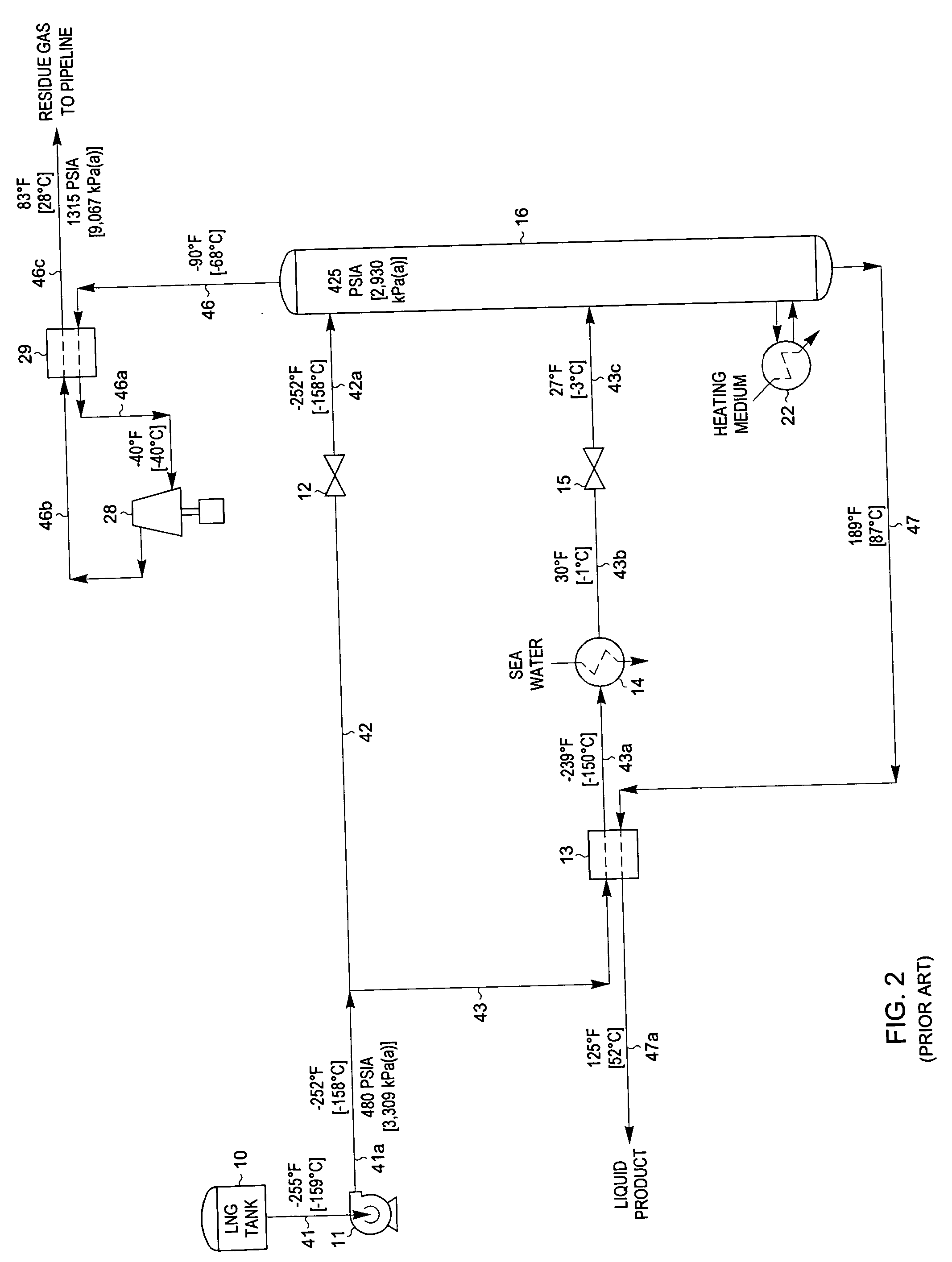
[0060] The present invention can also be adapted to produce an LPG product containing the majority of the C3 components and heavier hydrocarbon components present in the feed stream as shown in FIG. 11. The LNG composition and conditions considered in the process presented in FIG. 11 are the same as described previously for FIGS. 2, 5, and 8. Accordingly, the FIG. 11 process of the present invention can be compared to the prior art processes displayed in FIGS. 2, 5, and 8.
[0061] The processing scheme for the FIG. 11 process is essentially the same as that used for the FIG. 10 process described previously. The only significant differences are that the heat input of reboiler 22 has been increased to strip the C2 components from the liquid product (stream 47) and the operating pressure of fractionation tower 16 has been raised slightly.
[0062] The liquid product stream 47 exits the bottom of deethanizer 16 at 189° F. [87° C.], based on an ethane to propane ratio of 0.020:1 on a molar ...
example 3
[0066] If a slightly lower recovery level is acceptable, another embodiment of the present invention may be employed to produce an LPG product using much less power and high level utility heat. FIG. 12 illustrates such an alternative embodiment. The LNG composition and conditions considered in the process presented in FIG. 12 are the same as those in FIG. 11, as well as those described previously for FIGS. 3, 6, and 9. Accordingly, the FIG. 12 process of the present invention can be compared to the embodiment displayed in FIG. 11 and to the prior art processes displayed in FIGS. 3, 6, and 9.
[0067] In the simulation of the FIG. 12 process, the LNG to be processed (stream 41) from LNG tank 10 enters pump 11 at −255° F. [−159° C.]. Pump 11 elevates the pressure of the LNG sufficiently so that it can flow through heat exchangers and thence to absorber column 16. Stream 41a exiting the pump is heated first to −91° F. [−69° C.] in reflux condenser 17 as it provides cooling to the overhea...
PUM
 Abstract
Description
Claims
Application Information
 - R&D
- Intellectual Property
- Life Sciences
- Materials
- Tech Scout
- Unparalleled Data Quality
- Higher Quality Content
- 60% Fewer Hallucinations
Browse by: Latest US Patents, China's latest patents, Technical Efficacy Thesaurus, Application Domain, Technology Topic, Popular Technical Reports.
© 2025 PatSnap. All rights reserved.Legal|Privacy policy|Modern Slavery Act Transparency Statement|Sitemap|About US| Contact US: help@patsnap.com


