Safe liquid source containers

a liquid source and container technology, applied in the field of vapor source containers, can solve the problems of unsafe bubbler type sources, increased pressure inside the source bottle, safety and contamination risks, etc., and achieve the effect of relieving any additional excess pressur

Active Publication Date: 2005-03-31
ASM INTERNATIONAL
View PDF28 Cites 438 Cited by
  • Summary
  • Abstract
  • Description
  • Claims
  • Application Information

AI Technical Summary

Benefits of technology

[0021] In one embodiment, the by-pass conductance is provided by openings in a bubbler tube providing conductance from an inner gas volume within the container to the inlet, thereby by-passing the liquid phase. In another embodiment, the by-pass conductance is provided by a capillary tube in communication with the inner gas volume and the inlet. I...

Problems solved by technology

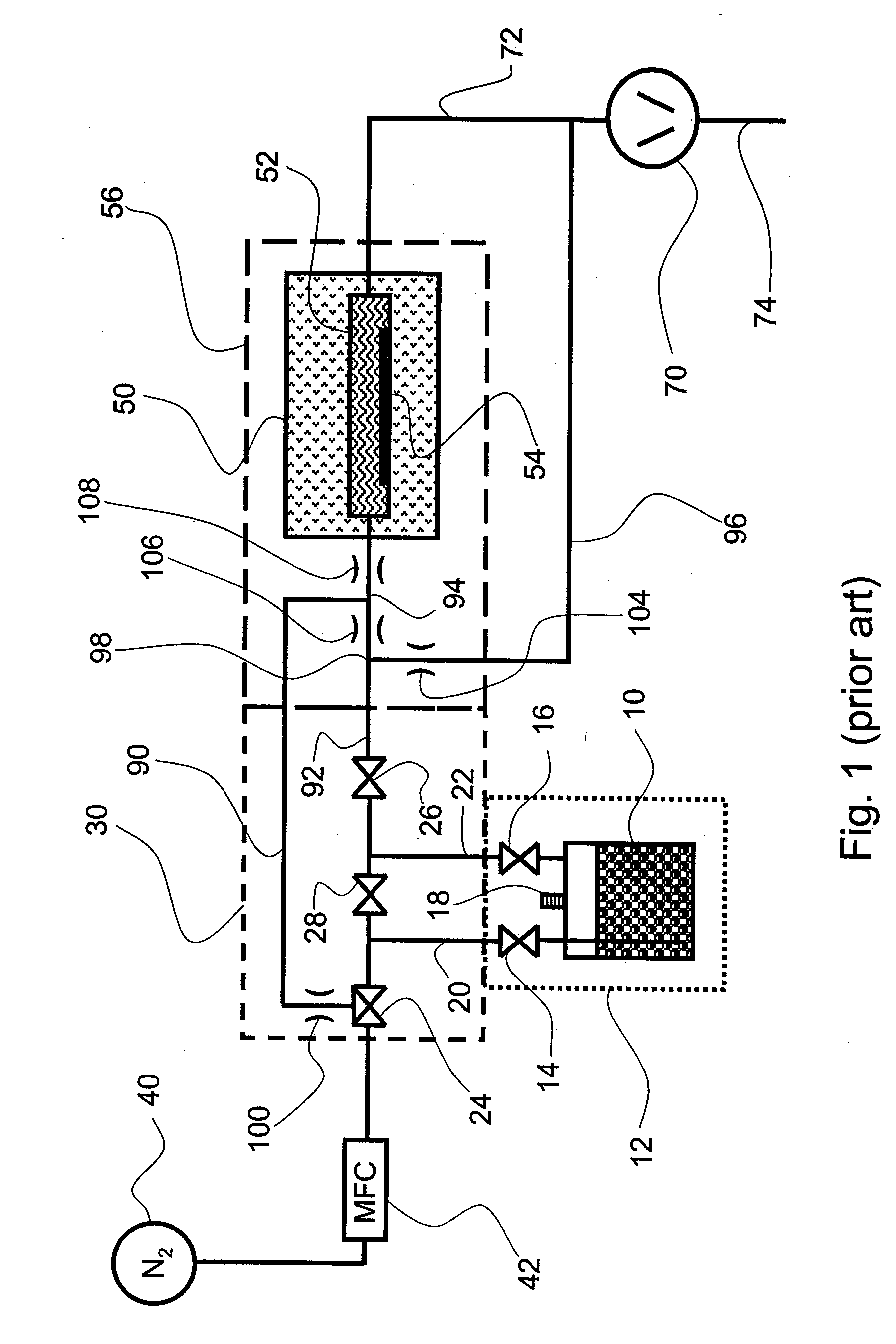
On the other hand, bubbler type sources are not always safe.
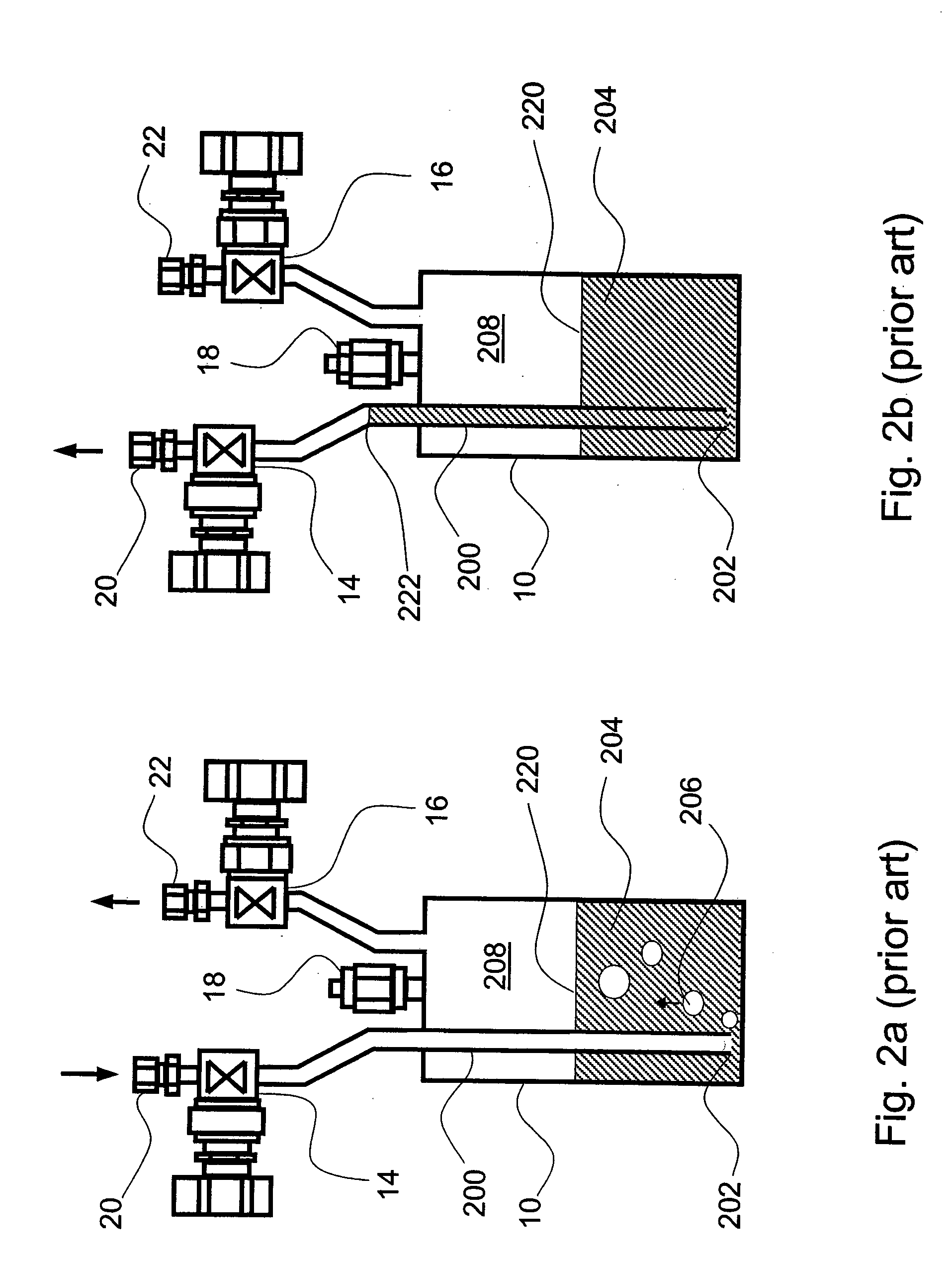
Under certain conditions there is risk that the pressure inside the source bottle is higher than in the inlet feeding tube (which is submerged in the liquid source).
This uncontrolled situation is a safety and contamination risk.
This type of risk is higher with ALD reactors due to the fact that the operation is based on pulsing and there is typically more than one route for the gases into the reactor.
These conditions increase the risk of accidentally pumping the gas inlet tubing to a lower pressure than the liquid container.
In other arrangements, the pulsing sequence can be more complicated.
It will be understood that certain problems related to the liquid source are created with the source pulsing method.
This is problematic, especially in liquid sources that undergo rapid pressure variations during ALD processing.
A backlash valve (not shown) placed ...

Method used


Image

  • Safe liquid source containers
  • Safe liquid source containers
  • Safe liquid source containers

Examples


Embodiment Construction

[0041] A number of embodiments are provided for a liquid source chemical apparatus that provides a vapor form of the source while minimizing the risk of liquid travelling backwardly through a carrier gas inlet tube. Certain of the embodiments provide such safety in the form of modifications to conventional “overflow” type of liquid sources, wherein the carrier gas tube is not submerged in the liquid, whereas other embodiments provide bubblers with modifications to inhibit liquid backflow through the carrier gas tube. Still other embodiments provide a novel structure employing semi-porous membranes for the carrier gas such that no route is provided for liquid flow out of the container during normal operation, and rather only vapor passes through the semi-porous membrane. Several of the embodiments employ porous elements at the interface between gas and vapor phases, advantageously enabling increasing the surface area of the interface either by way of the surfaces defined by the incre...


PUM

PropertyMeasurementUnit
Fractionaaaaaaaaaa
Fractionaaaaaaaaaa
Fractionaaaaaaaaaa

Abstract

Containers for providing vapor phase reactant from liquid sources include bubbler designs and designs in which carrier gas flows over the liquid surface. Among the bubbler arrangements, a bypass conductance is provided to release excess pressure from the gas volume inside the container, or an enlarged bubbler tube is provided with a volume sufficient to accommodate all possible liquid backflow without having the liquid exit the container. Among the overflow designs, flow dividers provide a tortuous path for the gas to increase the time exposure of carrier gas packets to the evaporating liquid surface. The flow dividers can be microporous to encourage capillary action, thereby increasing the evaporating surface. The tortuous gas flow path can be separated from the liquid phase by a breathable semi-porous membrane that permits vapor phase reactant to pass through but prohibits liquid from passing in the other direction.

Description

FIELD OF THE INVENTION [0001] The present invention relates generally to vapor source containers and more particularly, to liquid source containers used for generating vapor precursor to be used in downstream chemical reactions. BACKGROUND OF THE INVENTION [0002] Bubbler-type liquid sources are often used in chemical reactors, such as semiconductor processing tools. Examples include chemical vapor deposition (CVD) and atomic layer deposition (ALD) reactors. Bubblers tend to exhibit better efficiency than so-called “overflow” sources, in which vaporization depends on heating and the carrier gas simply flows over the surface of liquid, rather than being bubbled through the liquid. The efficiency of the overflow sources depends greatly on flow conditions. On the other hand, bubbler type sources are not always safe. Under certain conditions there is risk that the pressure inside the source bottle is higher than in the inlet feeding tube (which is submerged in the liquid source). The hig...

Claims


Application Information

Patent Timeline
IPC IPC(8): C23C16/448
CPCC23C16/4481Y10S261/65C23C16/4482
Inventor SOININEN, PEKKA T.
Owner ASM INTERNATIONAL
Why Eureka
Try Eureka