Hydraulic piston pump

Active Publication Date: 2011-04-21
ROBERT BOSCH GMBH
View PDF8 Cites 2 Cited by
  • Summary
  • Abstract
  • Description
  • Claims
  • Application Information

AI Technical Summary

Benefits of technology

[0007]A piston pump as defined by the characteristics of claim 1 has the advantage over the prior art that excessive pressure increases in the pump interior, with the attendant loads on the pressure-impinged components, are reduced. The means proposed for this develop their action only as needed, or in other words when the pressure level in the interior of the piston pump has exceeded a threshold value. Below that threshold value, the proposed means are inactive, since because of their greater flow resistance, pressure fluid does not flow th

Problems solved by technology

, which leads to a pressure increase in the interior of the piston pump and thus to an increased load

Method used


Image

  • Hydraulic piston pump
  • Hydraulic piston pump
  • Hydraulic piston pump

Examples


Embodiment Construction

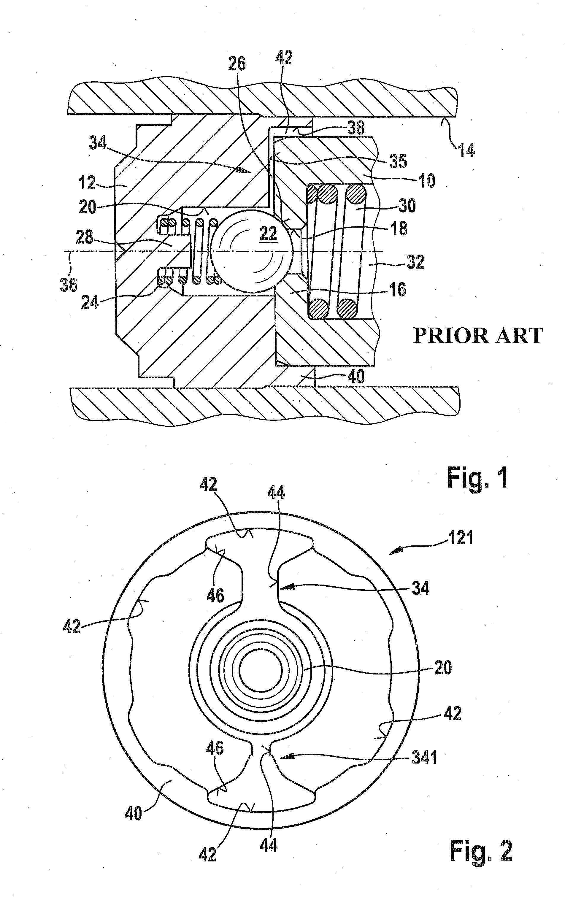
[0018]FIG. 1 shows the outlet region of a piston pump known from the prior art (see for instance DE 199 28 913 A1). The portion of a bush 10 can be seen as well as a closure stopper 12 on one face end of which the bush 10 rests. The closure stopper 12 and the bush 10 are inserted in a bore 14, shown in suggested fashion, of a pump housing, not shown, and the closure stopper 12 seals off this bore from the environment.

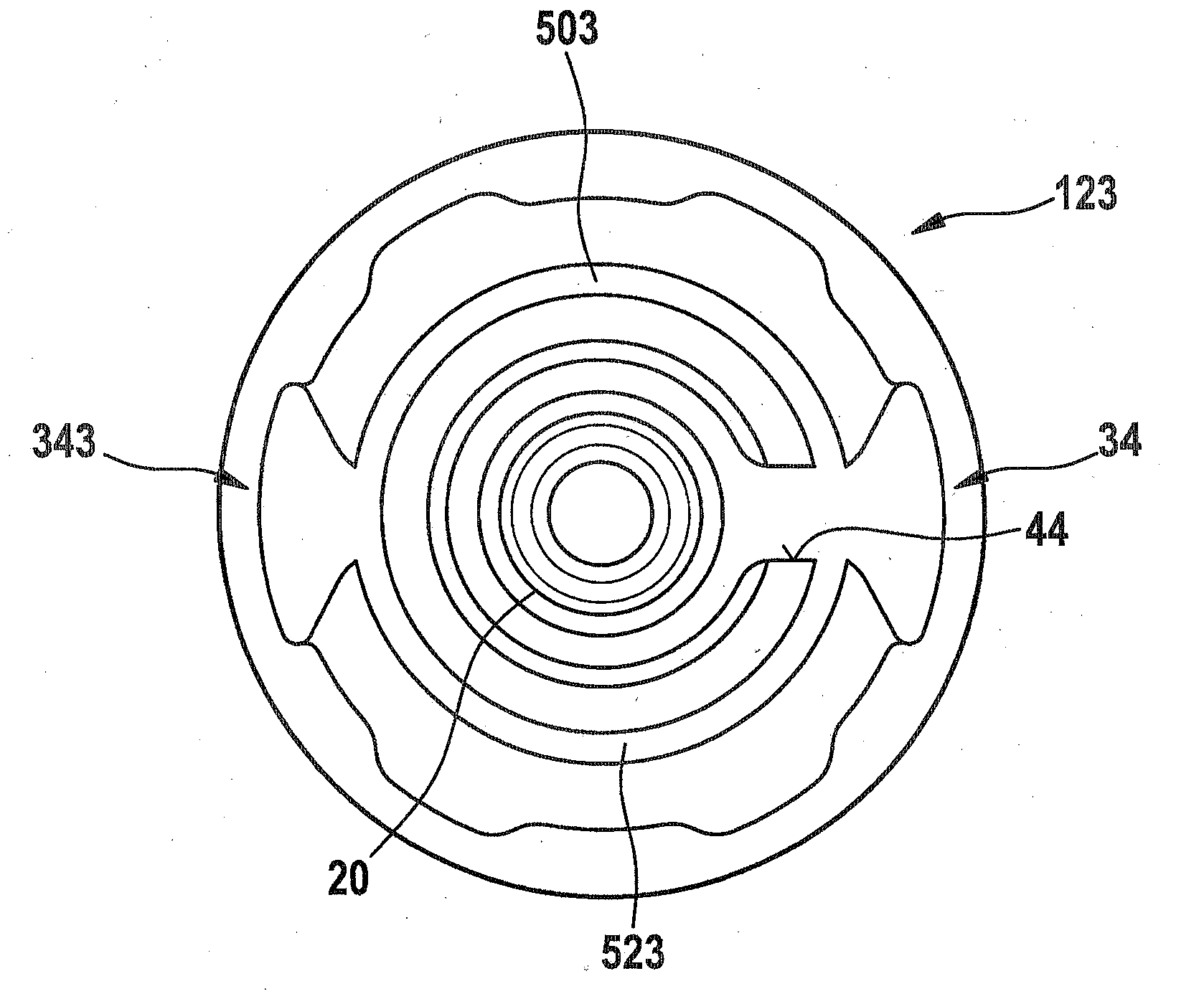
[0019]The bush 10 is embodied hollow-cylindrically and has a bush bottom 16 on its end toward the closure stopper 10. A through bore 18 is disposed centrally in the bush bottom 16. The through bore discharges into a valve chamber 20, which is embodied in the closure stopper 10. A valve closing body 22 in the form of a ball is received movably in this valve chamber 20. The valve closing body 22 is pressed by a valve spring 24 against a valve seat 26 on the face end of the bush 10. The valve spring 24 is braced for that purpose, by its end remote from the valve closing bo...


PUM


Abstract

The invention relates to a hydraulic piston pump, particularly for a slip-controllable vehicle braking system. A piston pump according to the invention includes a hydraulically permanently permeable stopper, the throughflow of which is carried out as a function of the pressure in an outflow channel of the piston pump. A pressure medium flow only takes place if the pressure level in the outflow channel has exceeded a threshold value. The latter takes place, for example, if the kinematic viscosity of the flowing pressure medium decreases due to low ambient temperatures, or if a throughflow of the outflow channel is obstructed. By means of the proposed solution, excess pressure increases in the interior of the piston pump can be avoided, and the resulting loads for the pressurized pump components and the drive can be reduced. Otherwise, the operating behavior of the piston pump according to the invention corresponds to that of a known piston pump.

Description

PRIOR ART[0001]The invention is based on a hydraulic piston pump, in particular for a vehicle brake system with electronic traction control, as generically defined by the characteristics of the preamble to claim 1.[0002]Brake systems with electronic traction control are also known as ABS / TC / ESP brake systems. These brake systems, for regulating the brake pressure at the individual wheel brakes as a function of any wheel slip that might occur, have a hydraulic unit that is triggerable by an electronic control unit. This hydraulic unit includes a metal housing block, with hydraulic components secured to the block. The piston pumps on which the invention is based form a substantial part of these hydraulic components. They are needed for supplying pressure fluid inside the hydraulic system of a vehicle brake system.[0003]From German Patent Disclosure DE 199 28 913 A1, a piston pump as defined by the generic characteristics of the preamble to claim 1 is already known. This known piston p...

Claims


Application Information

Patent Timeline
IPC IPC(8): B60T13/18
CPCB60T8/4031B60T13/18F04B53/168
Inventor SCHULLER, WOLFGANGREINER, JUERGEN
Owner ROBERT BOSCH GMBH
Why Eureka
Try Eureka