Tube bundle heat exchanger comprising tubes with expanded sections

a heat exchanger and tube bundle technology, applied in indirect heat exchangers, machines/engines, lighting and heating apparatus, etc., can solve the problems of prone to stress-induced failure, reduce the service life of the heat exchanger, so as to reduce the material cost and the effect of enlarged cross-sectional area

Inactive Publication Date: 2005-03-31
DANA CANADA CORP
View PDF42 Cites 67 Cited by
  • Summary
  • Abstract
  • Description
  • Claims
  • Application Information

AI Technical Summary

Benefits of technology

[0009] In one aspect, the present invention provides a heat exchanger comprising a plurality of tubes extending in parallel relation to one another and defining a tube axis. Each of the tubes comprises a pair of open ends, a tube wall extending between the ends and defining a hollow interior, a portion having an enlarged cross-sectional area and a portion having a relatively smaller cross-sectional area, both the enlarged portion and the smaller portion extending parallel to the tube axis. The enlarged portion of each of the tubes has a cross-sectional shape comprising a plurality of corners and a plurality of side surfaces extending between the corners, the side surfaces being generally parallel to the tube axis. The tubes are arranged as a tube bundle in which a first plurality of the tubes comprise inner tubes and a second plurality of the tubes comprise outer tubes, the outer tubes being located on a periphery of the tube bundle. The enlarged portion of each of the tubes abuts the enlarged portion of at least one other tube, the enlarged portions being in abutment with one another along their side surfaces, with sealed connections being provided between abutting pairs of the side surfaces to prevent axial flow of a fluid between the abutting side surfaces, and with interstitial spaces being formed between the smaller portions of adjacent tubes. The enlarged portion of each of the inner tubes abuts the enlarged portions of adjacent tubes along all of its side surfaces, with at least one side surface of the enlarged portion of each outer tube facing generally radially outwardly and not being connected to the side surface of the enlarged portion of an adjacent tube, the radially outwardly facing surfaces defining the periphery of the tube bundle. The heat exchanger further comprises an annular header ring extending about the periphery of the tube bundle which is connected to the enlarged portions of the outer tubes.
[0010] In another aspect, the present invention provides a method for manufacturing a heat exchanger. The method comprises providing a plurality of tubes, each of which comprises a tube wall and a hollow interior defined by the tube wall. Each tube has opposite end portions of enlarged cross-sectional area and a central portion of relatively smaller cross-sectional area, the enlarged portions and the central portion being concentric, each of the end portions having a cross-sectional shape comprising a plurality of corners and a plurality of side surfaces extending between the corners, the end portions of at least some of the tubes being provided with indentations in at least some of the side surfaces. The method further comprises forming the tubes into a tube bundle in which the tubes are in parallel relation to one another and define a tube axis. The side surfaces of the end portions and the central portions extend parallel to the tube axis, each of the tubes in the bundle being arranged to have its end portions abutting the end portion of at least one other of the tubes and its central portion spaced from the central portions of the other tubes in the bundle. The end portions abut one another along their side surfaces to form a plurality of facing pairs of side surfaces, and the indentations in the side surfaces of the end portions form voids between the facing pairs of side surfaces. The method further comprises at least partially filling each of the voids with a filler metal-forming material, the filler metal-forming material being sufficient to form a sealed connection between each facing pair of the side surfaces. The method further comprises heating the tube bundle to a sufficient temperature and for a sufficient time to cause the filler metal-forming material to liquefy and form a filler metal, the filler metal flowing into areas between the facing pairs of side surfaces. Lastly, the method comprises cooling the tube bundle to solidify the filler metal and thereby form a sealed connection between each of the facing pairs of side surfaces.

Problems solved by technology

Such joints provide a relatively small sealing surface and are prone to stress-induced failure.
However, increasing the thickness of the header plate by a significant amount adds to the material cost and significantly increases the cost of tooling and the complexity of forming the holes in the header plate.
However, conventional tube bundle heat exchangers cannot easily accommodate small diameter tubes due to the complexity of stamping small-diameter holes, and the compounding difficulty of forming the holes in thicker header plate constructions.

Method used


Image

  • Tube bundle heat exchanger comprising tubes with expanded sections
  • Tube bundle heat exchanger comprising tubes with expanded sections
  • Tube bundle heat exchanger comprising tubes with expanded sections

Examples


Embodiment Construction

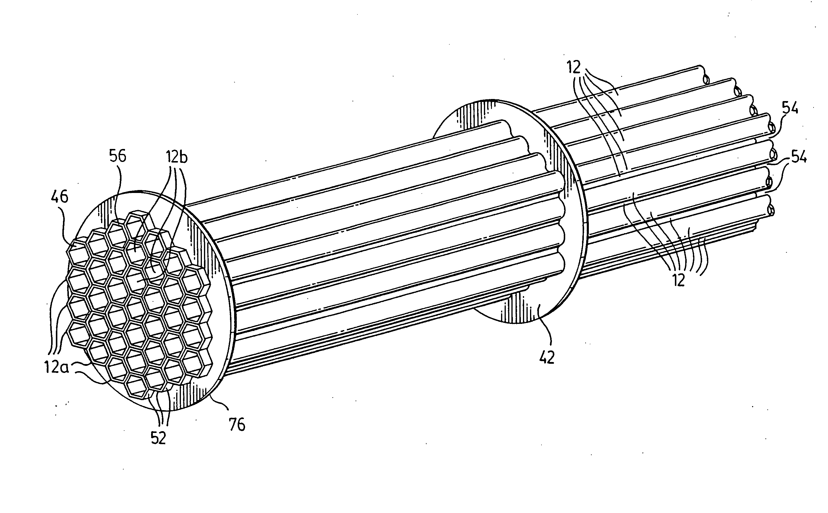
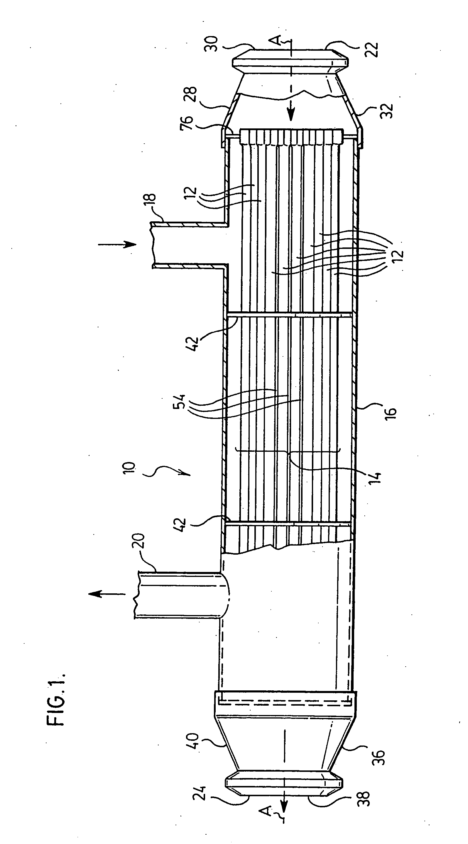
[0039]FIG. 1 illustrates a preferred heat exchanger 10 according to a first preferred embodiment of the invention. Heat exchanger 10 is particularly suited for use as a high temperature heat exchanger of the type where stress-induced failure of header plate joints would be of concern. For example, heat exchanger 10 can be used as an EGR cooler. It will also be appreciated that heat exchanger 10 may be adapted for use in a number of other automotive or non-automotive applications, including application to fuel cell fuel processors and fuel reformers.

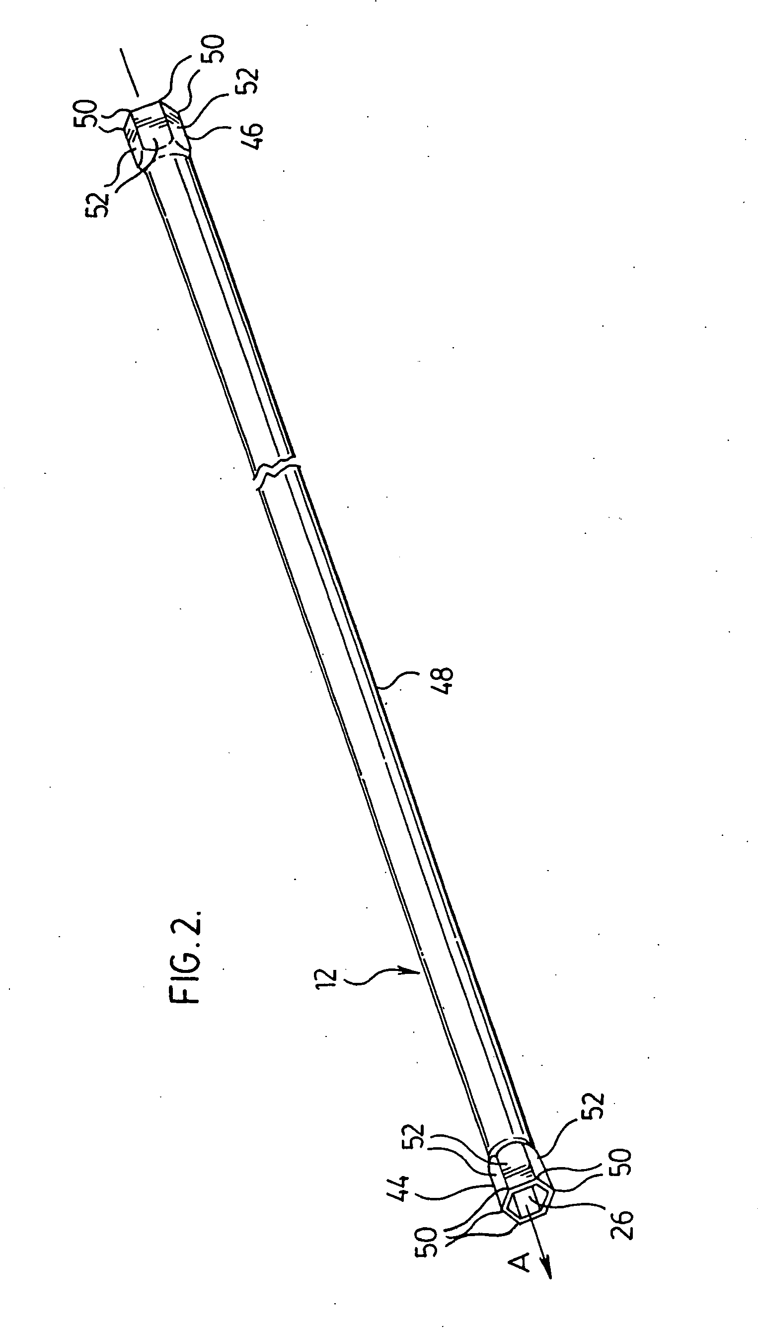
[0040] The heat exchanger 10 comprises a plurality of tubes 12 extending parallel to one another and defining a tube axis A. The tubes are arranged in the form of a tube bundle 14 which is more particularly described below with reference to FIGS. 3A and 3B. The tube bundle 14 is enclosed along, its sides by an axially extending outer shell or housing 16. The housing 16 is provided with a first inlet port 18 and a first outlet port 20 to ...


PUM


Abstract

A heat exchanger useful for high temperature applications such as EGR cooling and fuel reformer applications comprises a tube bundle made up of a plurality of tubes, each having at least one end expanded to an enlarged polygonal cross-section, and having central portions with a generally smaller cross section. When the tubes are formed into a bundle, the enlarged end portions nest with one another and interstitial spaces are provided between the central portions of the tube. The enlarged end portions are preferably retained by a header ring having a multifaceted inner peripheral sidewall which is adapted to form brazed lap joints with the outward facing surfaces of the peripheral tubes end portions in the tube bundle. In one preferred arrangement, axially aligned enlarged portions are provided intermediate the ends of at least some of the tubes. These enlarged intermediate portions nest with one another and eliminate or reduce the need for baffle plates.

Description

FIELD OF THE INVENTION [0001] This invention relates to heat exchangers of the type which comprise a bundle of spaced, parallel tubes and more particularly to such heat exchangers having tubes with expanded sections which permit the elimination of conventional headers and / or baffle plates. BACKGROUND OF THE INVENTION [0002] Tube bundle heat exchangers are used in a number of applications, and have been extensively used in automotive applications. Such heat exchangers typically comprise a bundle of spaced, parallel tubes enclosed in a housing or shell. A first heat exchange fluid flows through the tubes, while a second heat exchange fluid flows through the housing and passes through the interstitial spaces between the outer surfaces of the tubes. [0003] In a typical construction of a tube bundle heat exchanger, parallel tubes of circular cross-section are retained in place at their ends by perforated header plates, also known as tube sheets. In addition to retaining the tubes, the he...

Claims


Application Information

Patent Timeline
Patent Type & Authority Applications(United States)
IPC IPC(8): F02M26/00F28D7/16F28F9/02
CPCF02M25/0737F28D7/16F28D21/0003Y02T10/121F28F9/0221F28F9/182F28F21/08F28D2021/0043F02M26/32
Inventor WU, ALAN K.MARTIN, MICHAEL A.BROWN, ROBERT H.
Owner DANA CANADA CORP
Why Eureka
Try Eureka