Display dispenser

Inactive Publication Date: 2005-03-31
SOLO CUP OPERATING CORP
View PDF17 Cites 12 Cited by
  • Summary
  • Abstract
  • Description
  • Claims
  • Application Information

AI Technical Summary

Problems solved by technology

During periods of low volume or when fewer designs are being dis

Method used


Image

  • Display dispenser
  • Display dispenser
  • Display dispenser

Examples


Embodiment Construction

[0036] While this invention is susceptible of embodiment in many different forms, the drawings show and the specification describes in detail preferred embodiments of the invention. It should be understood that the drawings and specification are to be considered an exemplification of the principles of the invention. They are not intended to limit the broad aspects of the invention to the embodiments illustrated.

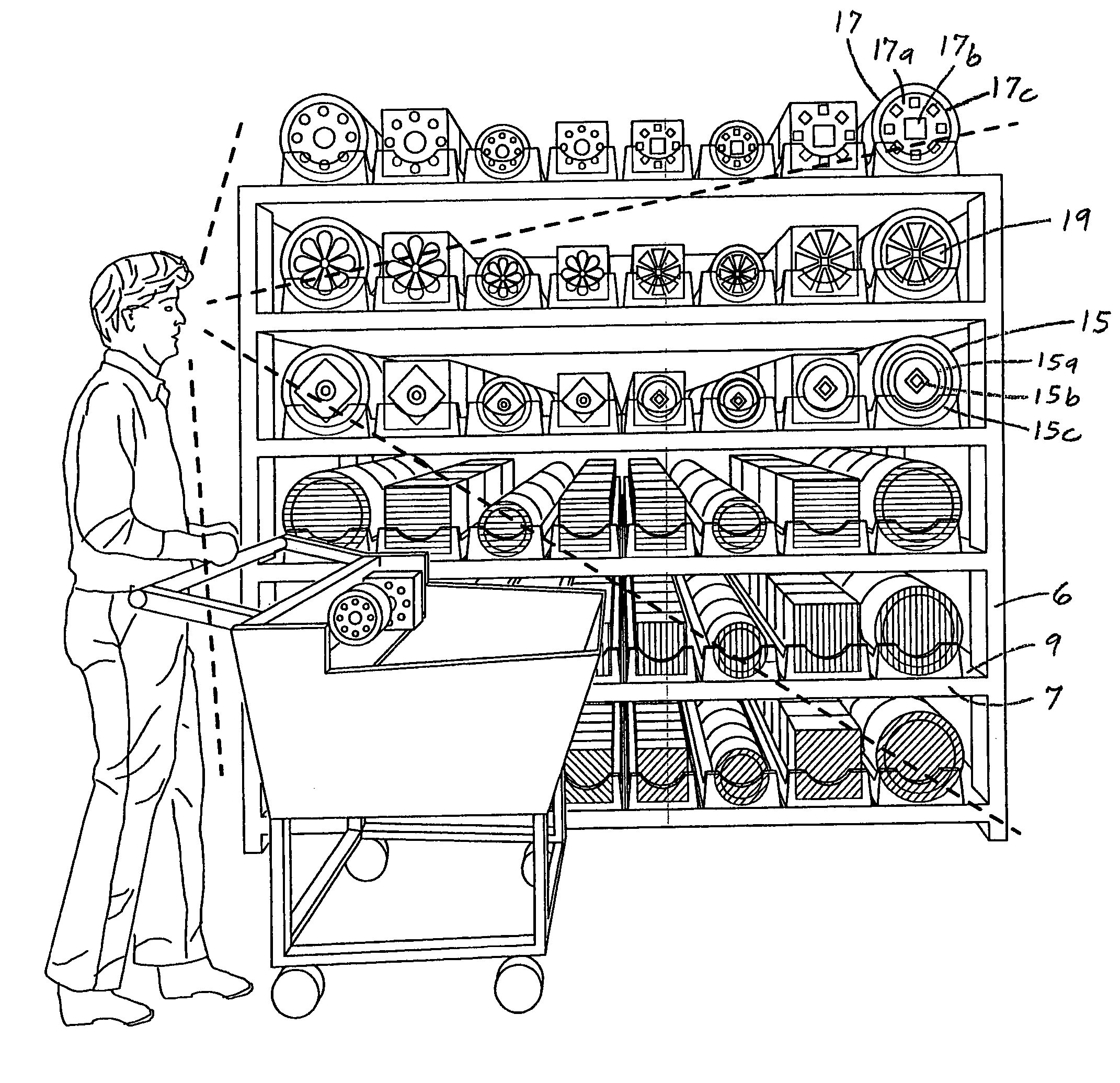
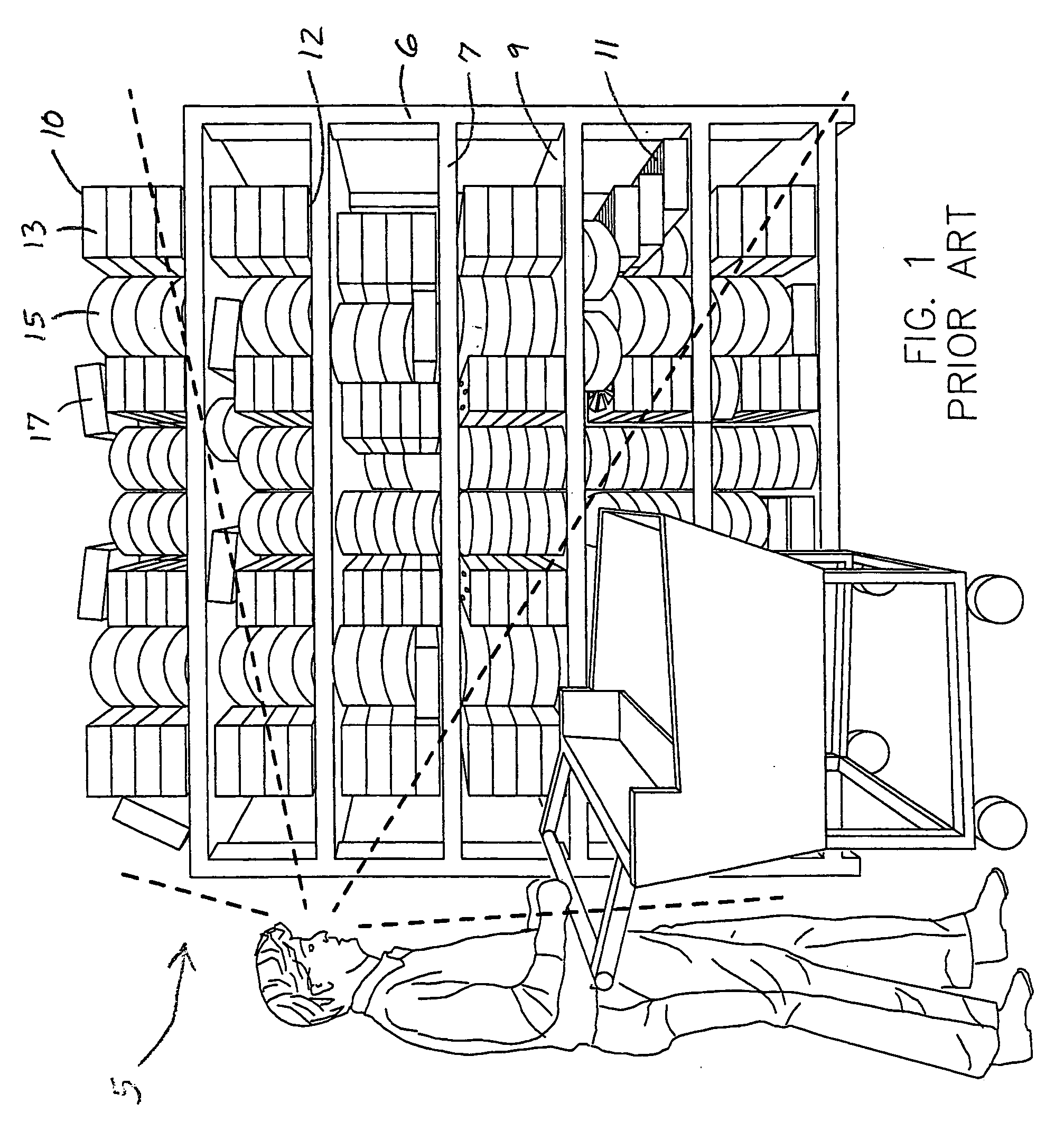
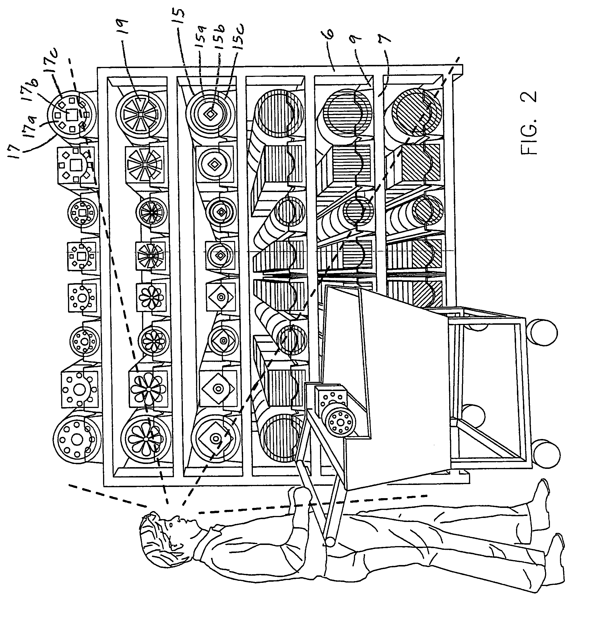
[0037] Retail and grocery stores present goods on shelving so that customers can easily move along aisles 5 to shop for articles or items they want to purchase as shown in FIG. 1. Each shelving unit 6 has a number of individual shelves 7 that are set one above the other and spaced apart so that each is at a different height. Each shelf 7 has a substantially flat and typically horizontal upper surface 9 upon which packaged goods 10 are placed. Some stores use shelves 7 that are slightly tilted or sloped toward the aisle 5 so that the products 10 on the upper shelves can be mo...


PUM


Abstract

The present invention pertains to a display dispenser having a disposable molded tray with a thin shell, unibody construction that firmly receives a removable pusher assembly. The tray is formed from a unitary sheet of plastic that forms inner and outer shells. Each shell forms the inside or outside half of a continuous wall around the perimeter of the tray. The two wall halves are integrally joined along a top portion, but otherwise spaced apart to provide a double-walled construction. Each wall has a frustoconical shape so that the trays nest into each other when stacked. The inner shell has an interior portion with two symmetrical side ledges that support and align the sides of the packages. The top of the package faces forward to show the artistic design on the article such as the paper plates or paper napkins inside. The inner shell has a central recess that snuggly receives the unified pusher assembly. A rim extending from the wall and a floor of the recess lay flat on a surface of a shelf.

Description

TECHNICAL FIELD OF THE INVENTION [0001] The present invention relates to a display dispenser with a disposable, thin shell, unibody tray and a separate, unified, snap-in pusher assembly, and is particularly suited for displaying and dispensing an assortment of packaged products in an organized and shoppable manner while accommodating ever changing shelving area requirements. BACKGROUND OF THE INVENTION [0002] Display dispensers are commonly used in retail and grocery store settings to organize items on store shelves and move those items forward toward the front of the shelf so that customers can easily see and reach the item. Each display dispenser contains a certain type of product, such as a bottle or box of pills. The product is placed in an upright position on the display, preferably with its label facing forward so that the customer can more readily identify the product. Items are placed on the display in a column. When the frontmost item is removed, the display causes the colu...

Claims


Application Information

Patent Timeline
IPC IPC(8): A47F1/12
CPCA47F1/126
Inventor HALBHERR, MICHAEL S.
Owner SOLO CUP OPERATING CORP
Why Eureka
Try Eureka