Radiographic image conversion panel and method for producing radiographic image conversion panel

a radiographic image and conversion panel technology, applied in the direction of conversion screens, instruments, nuclear engineering, etc., can solve the problems of radiographic image conversion panel poor graininess, image unevenness, and reduced sharpness, so as to improve the quality of radiographic images and good graininess

Inactive Publication Date: 2005-03-31
KONICA MINOLTA MEDICAL & GRAPHICS INC
View PDF2 Cites 16 Cited by
  • Summary
  • Abstract
  • Description
  • Claims
  • Application Information

AI Technical Summary

Benefits of technology

[0012] The present invention has been accomplished with the view to the above circumstance. An object of the present invention is to provide a radiographic image conversio

Problems solved by technology

However the photostimulable phosphor layer having the above-described column crystal structure has a problem that the crystal structure is disturbed on the interface of the support and excitation diode laser beam is diffused, thereby the sharpness is decreased.
Therefore

Method used


Image

  • Radiographic image conversion panel and method for producing radiographic image conversion panel
  • Radiographic image conversion panel and method for producing radiographic image conversion panel
  • Radiographic image conversion panel and method for producing radiographic image conversion panel

Examples


example 1

[0096] (Production of Radiographic Image Conversion Panel)

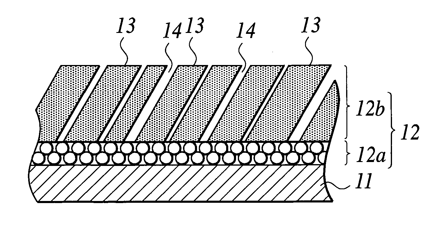
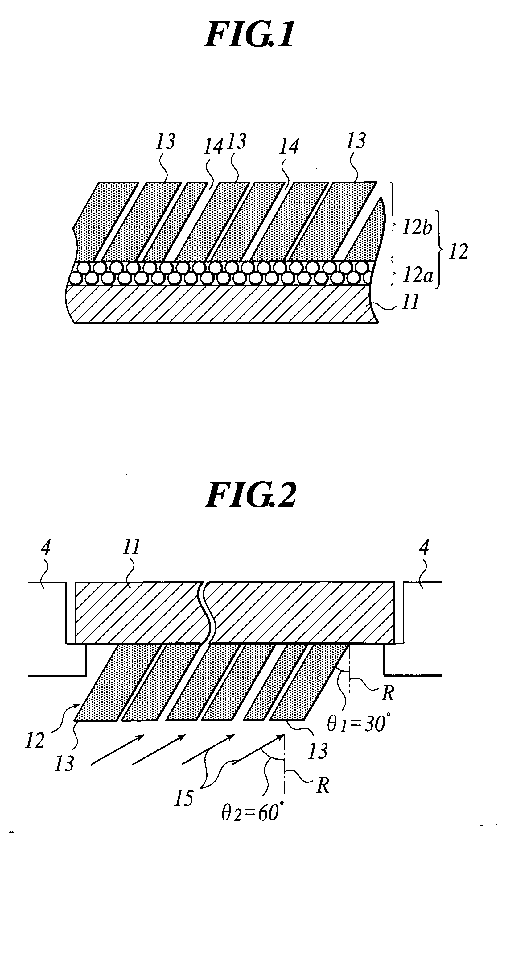
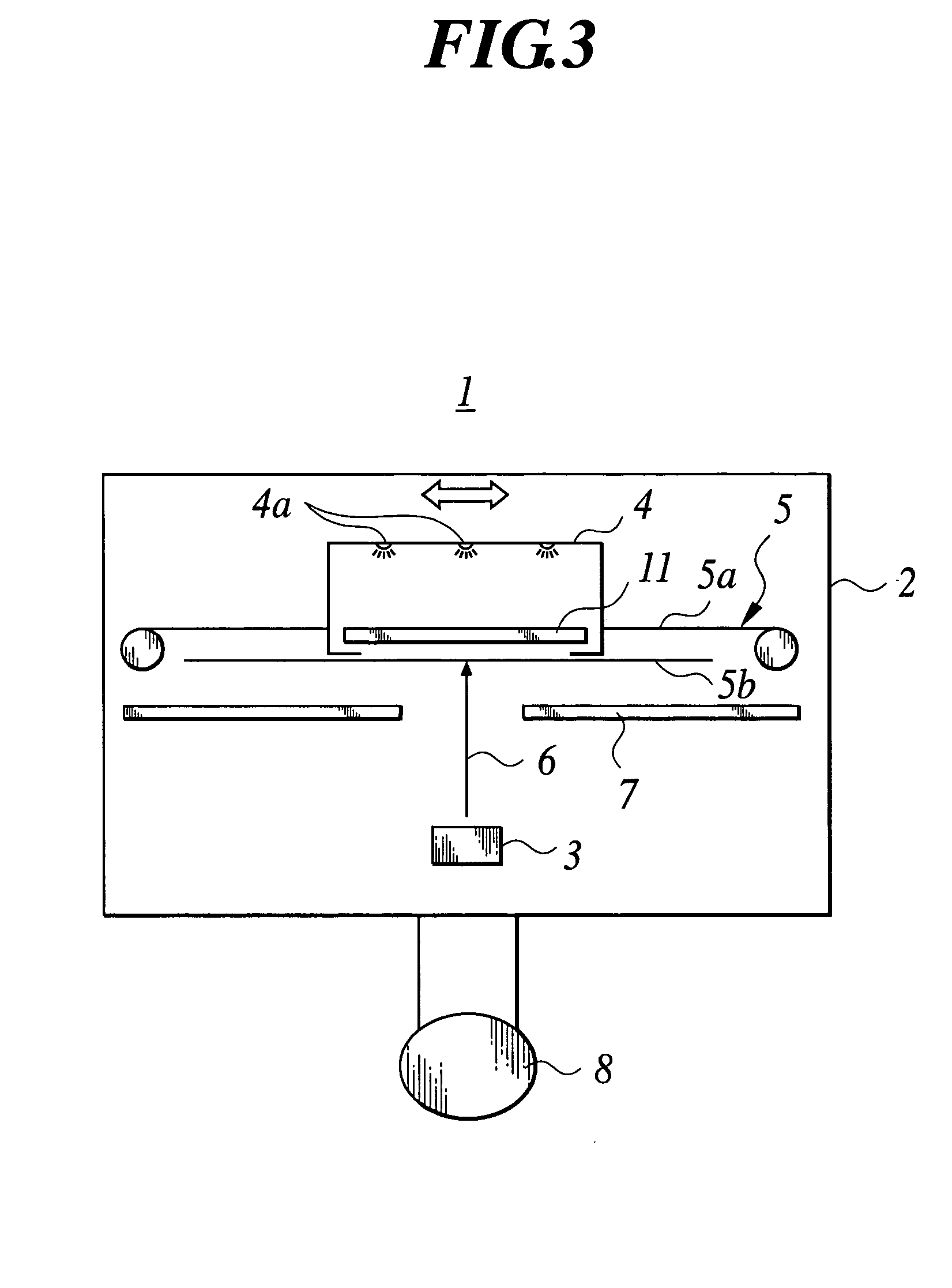
[0097] Onto the surface of a support of 1 mm-thick crystallized glass (manufactured by Nippon Electric Glass Co. Ltd.), a layer having the particle crystal structure containing a particle phosphor (CsBr:Eu) and then a layer having the column crystal structure containing a column phosphor (CsBr:Eu) were formed by use of the evaporation apparatus 1 shown in FIG. 3 (set θ1=5° and θ2=5° in FIG. 2).

[0098] That is, in the evaporation apparatus 1 shown in FIG. 3, a shield plate 7 made of aluminum was used and the distance between the support 11 and the shield plate 7 was 60 cm. Evaporation was performed while the support 11 was transported in the parallel direction to the support 11.

[0099] After the evaporation apparatus 1 was exhausted once, the vacuum was adjusted to 1.0×10⁻¹ Pa by introduction of Ar gas. The temperature of the support 11 is kept about 150° C. in evaporation, and evaporation was finished when the thickness of t...

example 2

[0103] Except that the thickness of the layer having the particle crystal structure was made 10 μm, a radiographic image conversion panel was produced in the same way as Example 1. In the obtained radiographic image conversion panel, the average particle size of particle phosphor was 3 μm and the average column diameter of column phosphor was 3 μm.

example 3

[0104] Except that the thickness of the layer having the particle crystal structure was made 100 μm, a radiographic image conversion panel was produced in the same way as Example 1. In the obtained radiographic image conversion panel, the average particle size of particle phosphor was 3 μm and the average column diameter of column phosphor was 3 μm.


PUM


Abstract

A radiographic image conversion panel includes: a support on which a photostimulable phosphor layer containing a photostimulable phosphor is formed; and a protective layer for covering the photostimulable phosphor layer, wherein the photostimulable phosphor layer comprises a layer having the particle crystal structure containing a particle phosphor provided on a side of the support, and a layer having the column crystal structure containing a column phosphor provided on a side of the protective layer.

Description

BACKGROUND OF THE INVENTION [0001] 1. Field of the Invention [0002] The present invention relates to a radiographic image conversion panel and a method for producing a radiographic image conversion panel made by forming photostimulable phosphor layer containing a photostimulable phosphor on a support and cover the photostimulable phosphor with a protective layer. [0003] 2. Description of Related Art [0004] Hitherto so-called radiation method using silver salt has been applied to obtain a radiation image. On the other hand, a method for imaging a radiation image without the use of the silver salt has been developed. That is, radiation passing through a subject is absorbed by a photostimulable phosphor. Then the photostimulable phosphor is excited by some sort of energy to be made to emit radiation energy stored in the photostimulable phosphor as a photostimulated luminescence, and the luminescence is detected to be transformed into an image. This method has been disclosed. [0005] As ...

Claims


Application Information

Patent Timeline
IPC IPC(8): G21K4/00C09K11/00C09K11/08C09K11/61C09K11/77C09K11/85G01T1/00G03B42/02G03B42/08
CPCG21K4/00C09K11/7733
Inventor YANAGITA, TAKAFUMIMISHINA, NORIYUKI
Owner KONICA MINOLTA MEDICAL & GRAPHICS INC
Why Eureka
Try Eureka