Vehicle wheel including spoke attachment

a technology for vehicle wheels and spokes, applied in the field of vehicle wheels, can solve the problems of increasing the weight of the wheel assembly, increasing the cost of manufacturing the hub component, and the multi-step machining process, so as to reduce the cost of machining operations, reduce the amount of material waste, and the effect of reducing the cost of machining

Inactive Publication Date: 2005-03-31
SCHLANGER RAPHAEL
View PDF10 Cites 18 Cited by
  • Summary
  • Abstract
  • Description
  • Claims
  • Application Information

AI Technical Summary

Benefits of technology

[0014] The present invention obtains many advantages. It is an advantage of the present invention is the reduction in cost through the ability to utilize inexpensive and efficient manufacturing techniques in the production of component parts.
[0015] The hub and hub flange of the present invention may be produced using “net shape” molding techniques that reduce or eliminate the need for expensive machining operations. Since this design is well suited to such molding or casting operations, the desired hub geometry may be produced with few, if any, secondary machining operations. In the case where subsequent machining is required, far fewer of these costly operations are anticipated than if the hub were produced from a billet or a forging. Further, in such a “net shape” forming operation, the amount of material waste is greatly reduced, particularly when compared to a part that is fully machined from billet.
[0016] While some existing wheel designs terminate the spoke in a pre-threaded hole in the hub flange, these tapping and threading operations are time consuming and expensive operations. The present invention allows the spoke to be anchored to a straight smooth cavity located in the rim or hub. Drilling or molding a straight and smooth cavity is far less expensive than providing a pre-threaded hole.
[0017] Since the spoke tension stresses of the present invention are distributed over a wider region of the hub flange interface, stresses are reduced within the hub flange material. Thus the strength requirements for the hub flange material are reduced and lower performance materials may be utilized, further reducing the cost as compared with conventional hubs. For example, the hub flange of the present invention may now be formed from relatively inexpensive polymer resins. These materials also lend themselves to lower-cost forming operations such as plastic injection molding. If a metallic hub flange is deemed necessary, high strength billet alloys are no longer required. Lower-strength metal casting alloys, which may be formed using a casting process such as die-casting, will likely have sufficient strength.
[0018] The present invention is uniquely applicable to arrangements wherein the hub flange and / or rim are formed from polymeric materials. Many of these materials, especially engineering polymers, exhibit good strength characteristics and are relatively inexpensive and easy to mold. Heretofore, these materials have not been used successfully applied in hub flange and rim applications because they do not exhibit sufficient hardness to withstand the high contact stresses associated with conventional spoke attachment technology. The present invention describes a longitudinal engagement between the spoke and the hub flange or rim. Such a longitudinal engagement increases the contact area and reduces the contact stress, making such polymer materials the preferred choice for forming the rim and / or hub flange.
[0019] Also, fiber reinforced injection molding compounds may now be utilized in the present invention. With these high strength composite polymers, the injection molding process permits the fibers to attain a generally random orientation within the matrix. This is a significant benefit that would not apply if the hub were machined from a fiber reinforced plastic billet. Fiber reinforced billet is normally produced by an extrusion process where the fibers become highly aligned in the direction of extrusion. Thus, a hub shell machined from such a billet would have relatively low strength perpendicular to the direction of extrusion.

Problems solved by technology

The manufacture of the hub component is an expensive process.
This multi-step machining process adds considerable expense to the manufacture of the hub shell component.
This requires that the hub flange construction be based on expensive, higher strength materials and the use of more expensive forming processes, such as forging, rather than less costly processes, such as die casting or injection molding.
Further, these stresses require that the flange be designed with robust thickness, thus adding weight to the wheel assembly.
Spoke manufacturers have attempted to compensate for this shortcoming by thickening the wire in this region, but this solution results in considerable extra expense and weight.
With a conventional hub flange, this creates a problem where the extra wide spoke cross section must pass through the round hole in the hub flange.
This additional operation adds considerable expense and weakens the hub flange as well.
This undesirable movement results in wear at the flange and additional flex at the rim and also causes the wheel to come out of alignment (true) rather easily.
Due to fabrication methods employed in conventional hub construction, it is very difficult to machine or otherwise create the details required to insure that the geometry of the hub flange conform to the spoke surface without any clearances.
This is obviously a compromise since, particularly in the case of bicycle wheels, the rim is of relatively light construction and any inconsistency in spoke tension or spoke flexure characteristics will cause the wheel to go out of true, or worse, will cause spoke breakage.
When the tensile loads are not evenly shared by all of the spokes, the spokes with greater stresses will be more prone to breakage as will the portions of the rim and hub flange associated with these spokes.

Method used


Image

  • Vehicle wheel including spoke attachment
  • Vehicle wheel including spoke attachment
  • Vehicle wheel including spoke attachment

Examples


Embodiment Construction

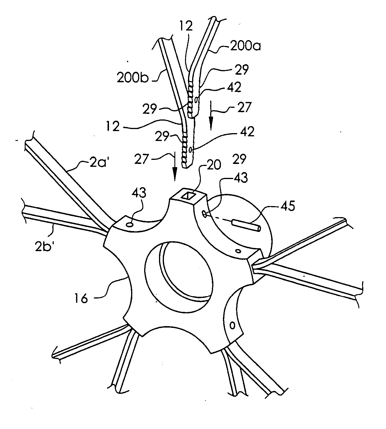
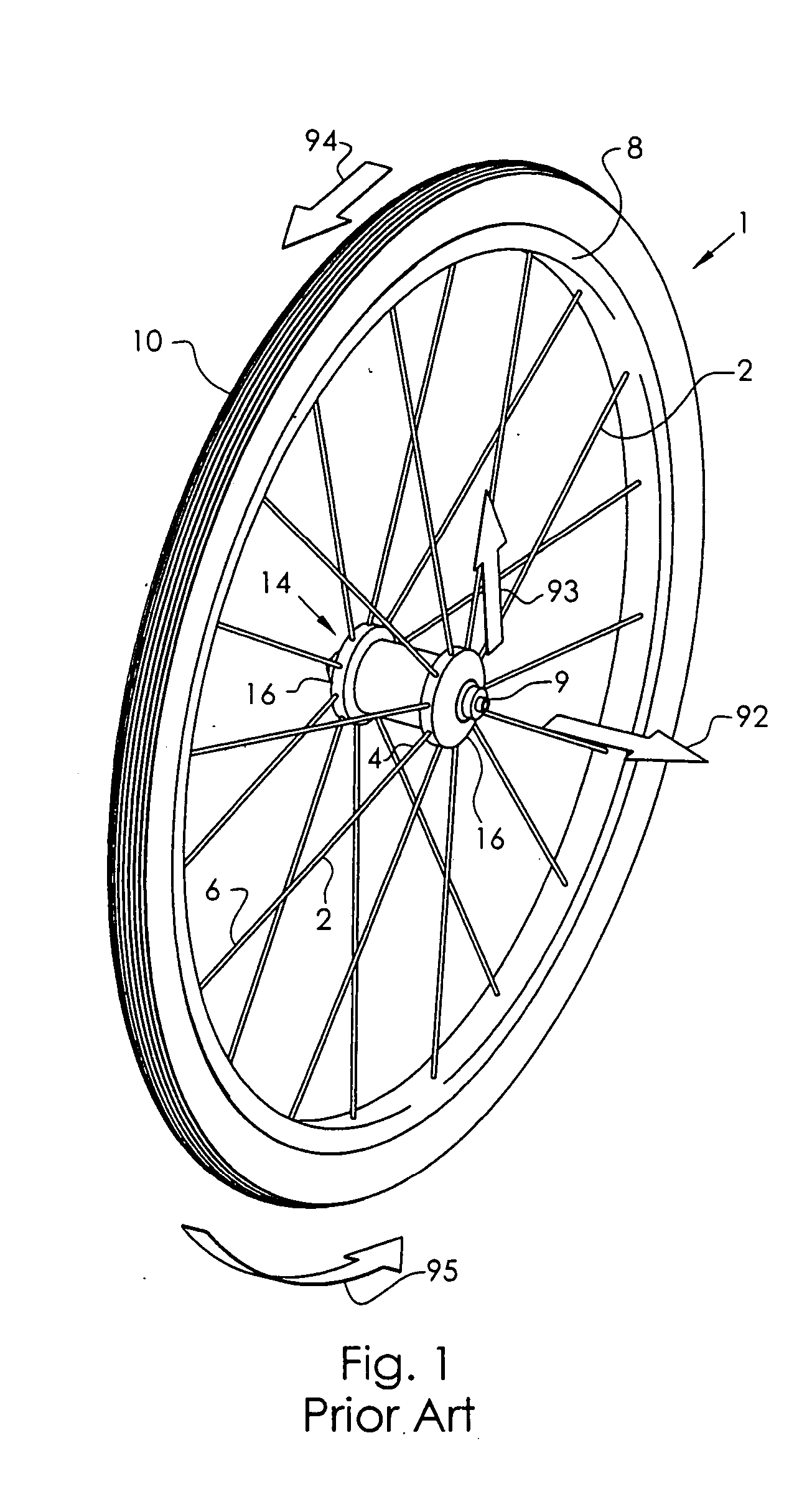
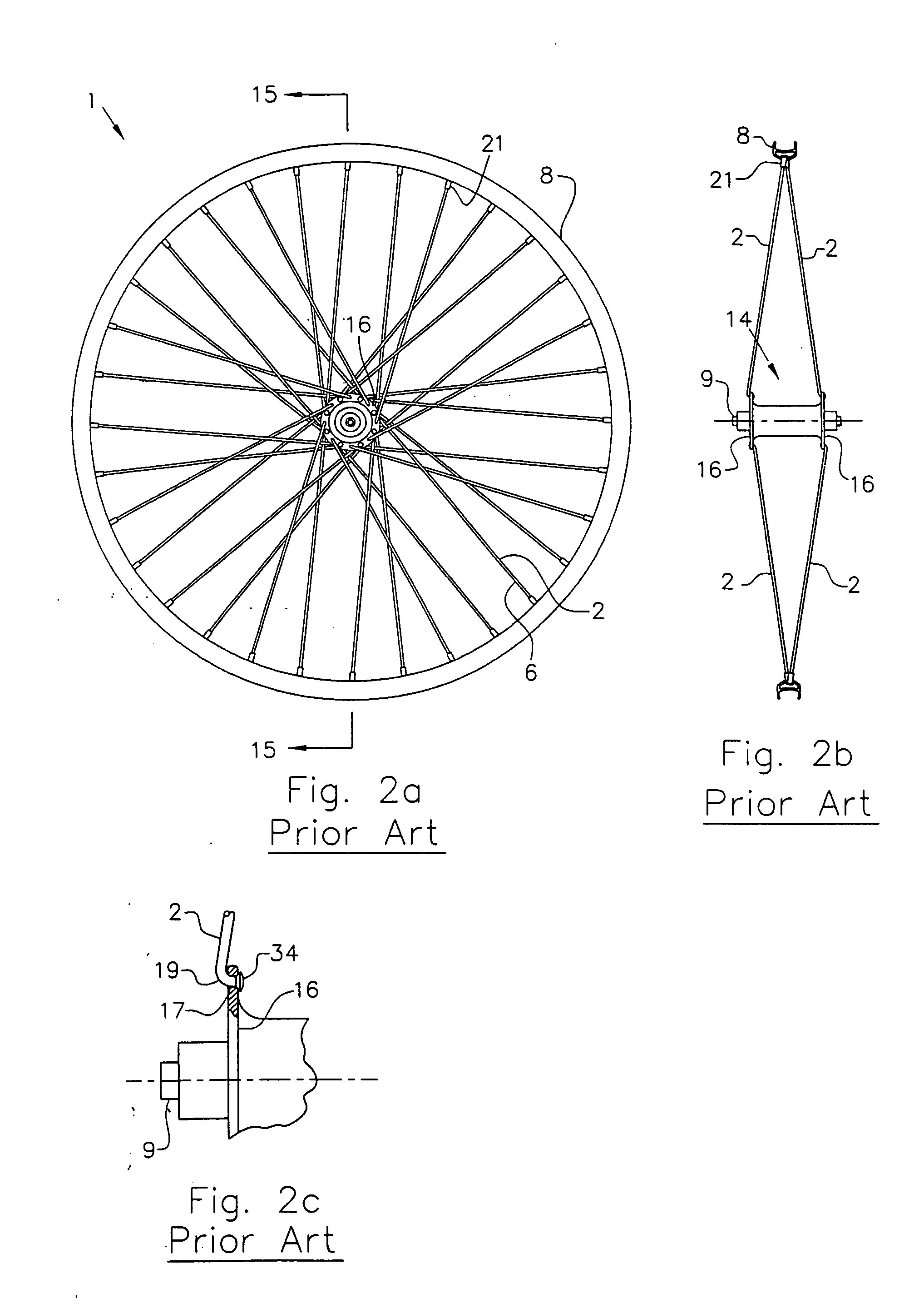
[0077]FIG. 1 describes the basic configuration of a vehicle wheel, in particular, a bicycle wheel 1, as well as a description of the direction conventions used throughout this disclosure. The hub shell 14 is rotatable about the axle 9 and includes at least two axially spaced hub or outer flanges 16, each if which include a means for connecting with the spokes 2. The hub flange 16 may be contiguous with the hub shell 14 or it may be separately formed and assembled to the body of the hub shell 14. The spokes are affixed to the hub flange 16 at their first end 4 and extend to attach the rim 8 at their second end 6. The tire 10 is fitted to the outer periphery of the rim 8. The axial direction 92 is any direction parallel with the axis of the axle 9. The radial direction 93 is a direction generally perpendicular to the axial direction 92. The tangential direction 94 is a direction within the plane of the rim 8 and perpendicular to the radial direction 93. The circumferential direction 9...


PUM


Abstract

The vehicle wheel includes an outer rim hoop with means for holding a tire, a plurality of spoke portions, and a central hub assembly. The central hub assembly includes an axle assembly and a hub shell that is rotatable about the axle. The hub shell includes at least two axially spaced outer flanges for attachment with the spokes. The spokes are connected at their outer ends to the rim hoop and at their inner ends to their respective outer flange. Firm attachment between the spoke and the outer flange is achieved by engaging of a portion of the spoke with a cavity formed within at least one of the rim and the outer flange. Also disclosed are attachment arrangements that include an intermediate connection member to facilitate attachment between the spoke and the cavity.

Description

CROSS-REFERENCE TO RELATED APPLICATION [0001] This application is a Continuation-In-Part of U.S. patent application Ser. No. 09 / 210,973, filed Dec. 14, 1998.BACKGROUND OF THE INVENTION [0002] This invention relates to vehicle wheels, specifically to the connection between the spoke and the hub and between the spoke and the rim. [0003] Heretofore, the vast majority of bicycle wheels have been constructed using steel wire spokes that are connected, at their inner end, to a central hub component and, at their outer end, to a metallic rim hoop. The spokes are generally of steel construction while the hub and rim may be of aluminum or steel construction. The spokes, hub and rim are each formed as separate components that are then joined together with mechanical connections. [0004] The manufacture of the hub component is an expensive process. Some hub shells are machined from aluminum billet while others are cast or forged and subsequently machined. This machining operation generally requ...

Claims


Application Information

Patent Timeline
Patent Type & Authority Applications(United States)
IPC IPC(8): B60B1/00B60B1/04
CPCB60B1/003B60B1/0269B60B1/0276B60B1/0284B60B1/041B60B1/042B60B2360/32B60B21/062B60B21/064B60B2310/204B60B2310/305B60B2310/306B60B2310/316B60B1/048B60B1/0261B60B27/023B60B27/026
Inventor SCHLANGER, RAPHAEL
Owner SCHLANGER RAPHAEL
Why Eureka
Try Eureka