Fluorescent lamp

a technology of fluorescent lamps and tubes, applied in vacuum tubes/containers/shields, instruments, and power sources with built-in power, etc., can solve the problems of high labor cost of said replacement, high electricity consumption, and complex replacement procedures of ballasts, so as to reduce installation costs, facilitate installation and replacement, and high power factor

Inactive Publication Date: 2005-03-31
SYNERGY LIGHTING GRP LTD
View PDF11 Cites 4 Cited by
  • Summary
  • Abstract
  • Description
  • Claims
  • Application Information

AI Technical Summary

Benefits of technology

This utility model has the advantages as follows: 1. Emergent illumination, electronic ballast and power-saving lightpipe are integrated, which results in convenient installation and replacement, and a significant decrease in the cost on installation; 2. It has a high power factor of more than 95%, and thus is electricity-saving and low in operational cost; 3. Color Rendering Index (CRI) is more than 80%; 4. It will illuminate as soon as being turned on, without flashing; 5....

Problems solved by technology

This kind of fluorescent lamp has the following defects: (1) it has a high electricity consumption; (2) it makes noises when the ballast works; (3) the replacement procedure of ballast is complex and the labor cost of said replacement is high; (4) the power factor and the intensity of illumination of the fluorescent lamp are low; (5) the lightpipe flashes when starting; (6) the lightpipe cannot remain bright when the power is cut off; (7) when the starter is worn out, the common lightpipe cannot be started as well; (8) the in...

Method used


Image

  • Fluorescent lamp
  • Fluorescent lamp
  • Fluorescent lamp

Examples


Embodiment Construction

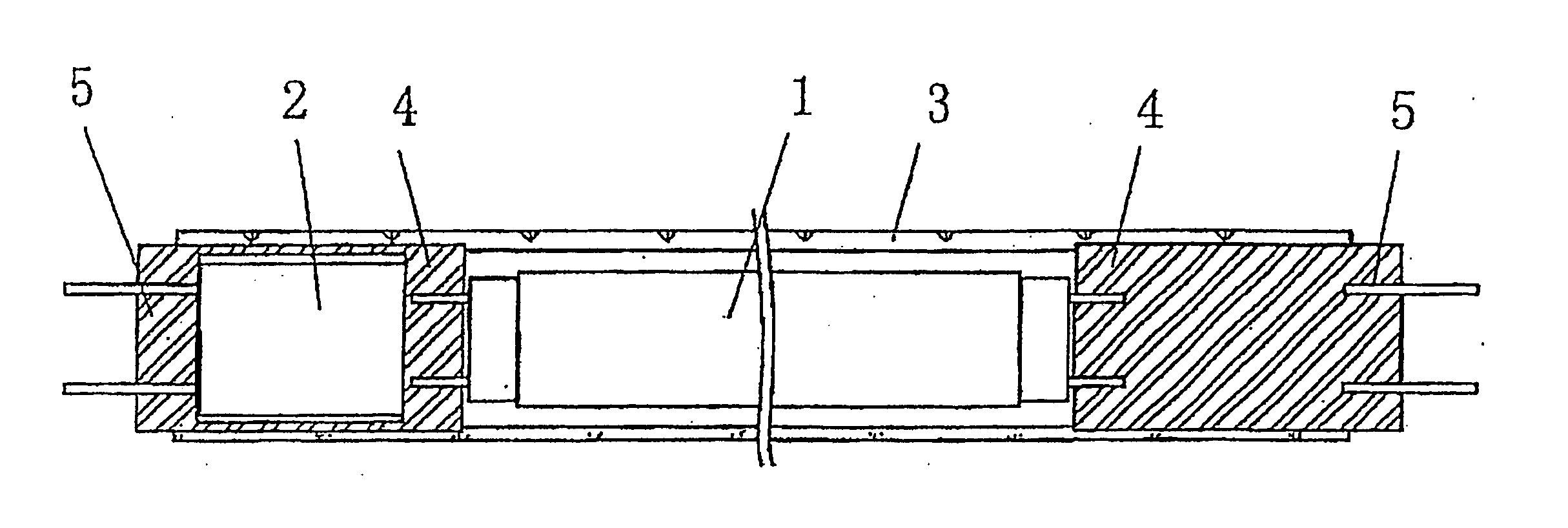
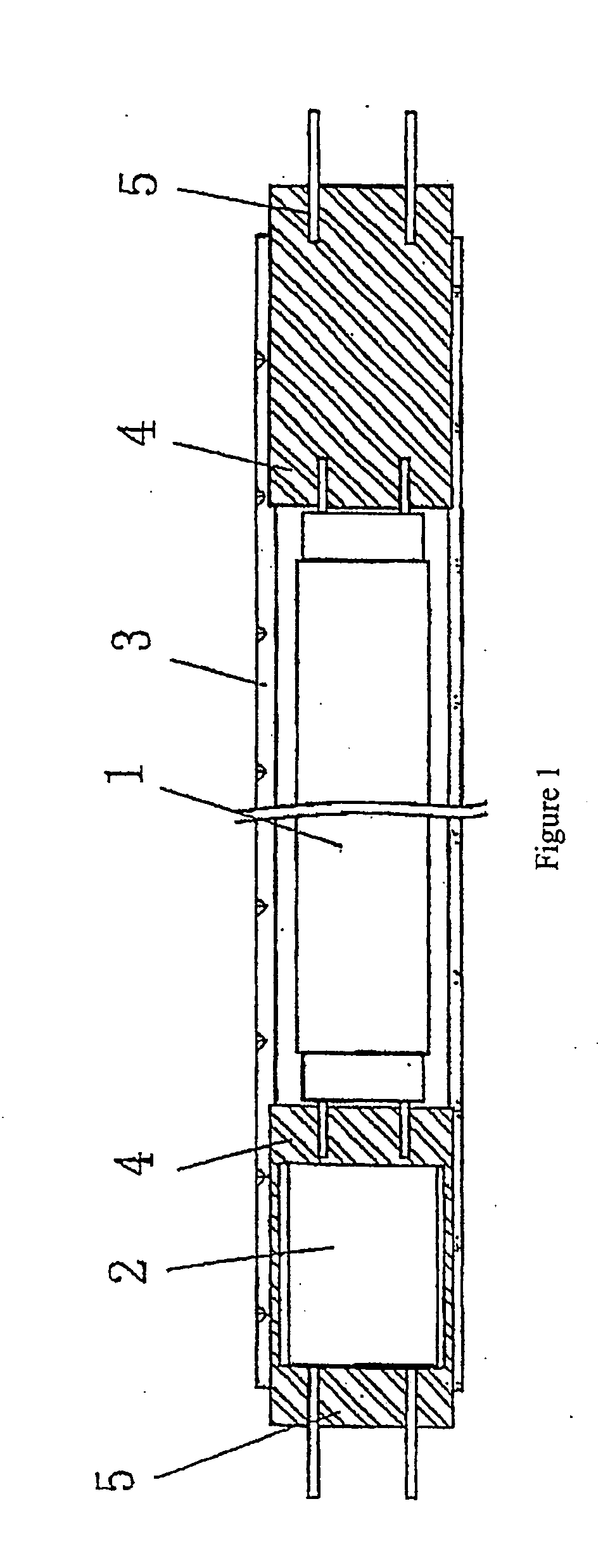
As shown in FIG. 1, the novel fluorescent lamp tube as provided in this utility model comprises a lamp tube 1, an electronic ballast2, and an outer tube 3 made of transparent materials (such as glass or transparent plastic), the two ends of which are fixed with outer plugs 5 of lamp tube sockets 4, wherein an electronic ballast 2 is equipped between one of said outer plugs 5 and the respective lamp tube socket 4. The lamp tube 1 is located between the two lamp tube sockets 4 in the outer tube 3. The lamp tube can be a power-saving one with a small diameter, and the outer plugs 5 are those at the two ends of an ordinary fluorescent lamp. These parts thereby form a novel power-saving fluorescent lamp tube capable of being directly equipped on the supporting bracket of a prior fluorescent lamp, and the electronic ballast is equipped in the fluorescent lamp tube, unnecessary to install another one. Therefore, the cost needed for said replacement will be decreased.

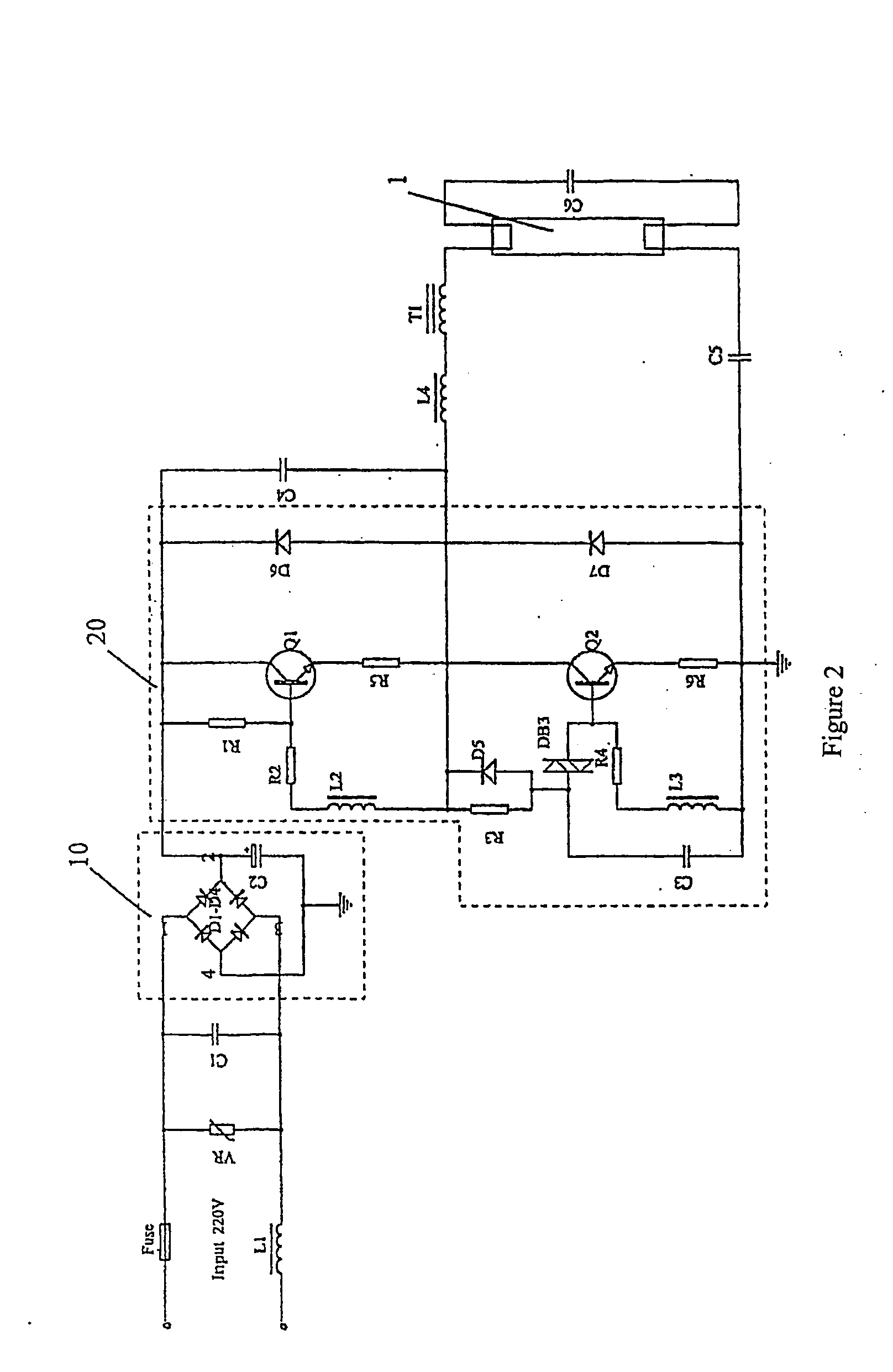
FIG. 2 is a circuit d...


PUM


Abstract

A new fluorescent lamp comprises a lamp tube and an electronic ballast, it is characterized in that it is provided with an outer tube, there are respectively an outer plug at both ends of the outer tube, in which inserts a socket for the lamp tube. The electronic ballast is between the outer plug and the socket for the lamp tube at one end, said lamp tube is disposed between two sockets for the lamp tube. There are advantages as follows: an urgent lighting, the electronic ballast and the compact lamp tube are integrated as one whole; it is convenient for mounting and exchanging, a cost for mounting is greatly reduced; it is possible for repacking to maintain an original means, to reduce a contamination of waste; its weight is light; its power factor is high, more than 95%, it is economical in power, a cost for transporting is low; the color rendering index (CRI) is more than 80%; it is ignited immediately after it is turned on, it does not flash; it is applied to lamps having deferent power; the life of the lamp tube is prolonged by 50%; its output brightness is higher than existing lamps by twice or more; the lamp tube still steadily operates when a power supply is unexpected to be shut off, which reduces accident cases; the whole distortion of a resonant wave becomes smaller than 30%.

Description

FIELD OF INVENTION The present invention relates to a fluorescent lamp tube. BACKGROUND OF INVENTION Currently, the widely used fluorescent lamp is comprised of a lamp tube, a ballast, a starter, and a metal bracket for supporting these parts. Most of the existing ballasts are inductive. This kind of fluorescent lamp has the following defects: (1) it has a high electricity consumption; (2) it makes noises when the ballast works; (3) the replacement procedure of ballast is complex and the labor cost of said replacement is high; (4) the power factor and the intensity of illumination of the fluorescent lamp are low; (5) the lightpipe flashes when starting; (6) the lightpipe cannot remain bright when the power is cut off; (7) when the starter is worn out, the common lightpipe cannot be started as well; (8) the inductive ballast is made of iron and copper, and thus not environment-friendly; (9) the metal bracket plus inductive ballast is over heavy; (10) the harmonic distortion is so h...

Claims


Application Information

Patent Timeline
IPC IPC(8): F21S2/00F21Y103/00F21S9/02H01J5/50H01J61/34H01J61/35H01J61/54H01J61/56H05B41/24
CPCH01J5/50H01J61/56H01J61/35H01J61/34
Inventor CHAN, KAM KWANNG, WAI KUEN
Owner SYNERGY LIGHTING GRP LTD
Why Eureka
Try Eureka