Method and system for robot localization and confinement

a technology for localization and confinement of robots, applied in vehicle position/course/altitude control, process and machine control, instruments, etc., can solve the problems of unintentional wandering of vacuuming robots working in one room from one room to another before satisfactorily, and inability to easily place doors or other physical barriers in the robot's exit path

Inactive Publication Date: 2005-03-31
IROBOT CORP
View PDF10 Cites 273 Cited by
  • Summary
  • Abstract
  • Description
  • Claims
  • Application Information

AI Technical Summary

Benefits of technology

[0019] It is an additional object of a preferred embodiment of the invention to provide a system that is substantially imp...

Problems solved by technology

By way of example, a vacuuming robot working in one room may unintentionally wander from one room to another room before satisfactorily completing the vacuuming of the first room.
In many houses, however, open passageways often separate rooms, and doors or other physical barriers cannot easily be placed in the robot's exit path.
Likewise, a user may desire to only have the robot operate in a portion of a single open space and, therefore, letting the robot work in the entire room decreases efficiency.
These systems require sophisticated hardware, such as precision sensors and significant computer memory and computational power, and typically do not adapt well to changes in the area in which the robot is working.
Likewise the robot cannot simply be taken from one building to another building, or even from room-to-room, without significant reprogramming or training.
Similarly, certa...

Method used


Image

  • Method and system for robot localization and confinement
  • Method and system for robot localization and confinement
  • Method and system for robot localization and confinement

Examples


Embodiment Construction

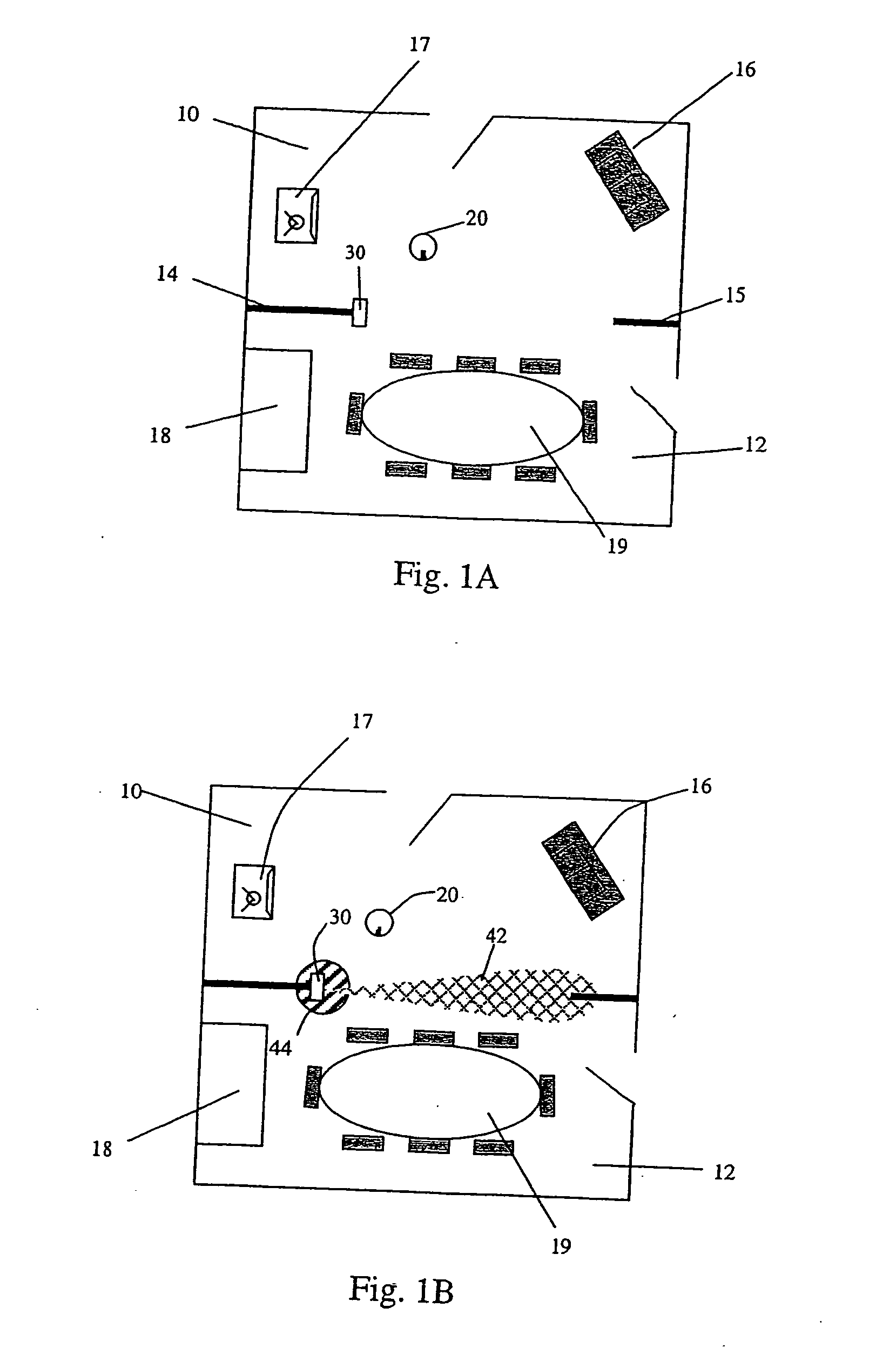
[0031] Referring to FIGS. 1A & 1B, living room 10 is shown separated from dining room 12 by interior walls 14&15. The living room and / or dining room may contain various furnishings, for example, couch 16, television 17, buffet 18 and table and chairs 19.

[0032] The rooms also contain a mobile robot 20 and a barrier signal transmitting device 30, which for purposes of this specification is also called a robot confinement (or RCON) transmitter 30. In FIGS. 1A & 1B, the robot is placed in the living room 10, and the RCON transmitter 30 is placed in the area dividing the living room 10 from the dining room 12, against interior wall 14 and pointing toward interior wall 15.

[0033] As described in more detail herein, FIG. 1B shows the same configuration of rooms with the RCON transmitter 30 in a powered state emitting, e.g., an infrared beam 42 from the RCON transmitter 30 toward interior wall 15. The beam 42 is directed primarily along an axis to create a boundary or barrier between livin...


PUM


Abstract

The present invention discloses a system and method for confining a robot to a particular space. The system includes a portable barrier signal transmitter that produces a barrier signal primarily along an axis, and a mobile robot capable of avoiding the barrier signal upon detection of the barrier signal. In the preferred embodiment the barrier signal is emitted in an infrared frequency and the robot includes an omni-directional signal detector. Upon detection of the signal, the robot turns in a direction selected by a barrier avoidance algorithm until the barrier signal is no longer detected.

Description

CROSS REFERENCE TO RELATED APPLICATIONS [0001] This application is related to and claims priority from U.S. Nonprovisional patent application Ser. No. 10 / 696,456, filed Oct. 29, 2003, which claims the benefit of priority from U.S. Nonprovisional patent application Ser. No. 10 / 056,804, filed Jan. 24, 2002, which claims the benefit of priority from U.S. Provisional Application Ser. No. 60 / 263,692, filed Jan. 24, 2001.BACKGROUND OF THE INVENTION [0002] The invention relates to a method and system for robot localization and confinement. [0003] There have been many systems proposed in the prior art for confining a robot to specific physical space for the purpose of performing work. These systems are typically designed for any number of robotic applications such as lawn care, floor cleaning, inspection, transportation, and entertainment, where it is desired to have a robot operate in a confined area for performing work over time. [0004] By way of example, a vacuuming robot working in one ...

Claims


Application Information

Patent Timeline
IPC IPC(8): G05D1/02
CPCA47L9/009G05D1/0214G05D1/0225G05D1/0227G05D1/0238G05D1/0234G05D1/0272G05D2201/0215A47L2201/04G05D1/028G05D1/0242
Inventor JONES, JOSEPH L.MASS, PHILIP R.
Owner IROBOT CORP
Why Eureka
Try Eureka