
Non-contact power supply system

a power supply system and non-contact technology, applied in the direction of electric variable regulation, process and machine control, instruments, etc., can solve the problems of poor usability for users, and ineffective power supply

Active Publication Date: 2005-03-31
SHARP KK
View PDF29 Cites 64 Cited by
  • Summary
  • Abstract
  • Description
  • Claims
  • Application Information

AI Technical Summary

Benefits of technology

[0012] In order to achieve the above object, the present invention provides a power supply system capable of supplying power from a power transmitter to a power receiver in an electrically non-contact manner. This power supply system includes: a power transmission module attached to the power transmitter; and a power reception module attached to the power receiver, wherein the power transmission module includes a plurality of transmission-side coils for transmitting power, the power reception module includes a plurality of reception-side coils for receiving power, and any of the transmission-side coils and any of the reception-side coils are operated in a combination realizing highest power transmission efficiency.
[0025] For example, the memory may record the value of the power energy only when the value of power energy to be recorded is equal to or larger than a predetermined value. Consequently, time of recording information onto the memory and time of comparing the value of the power energy with the other values of the power energy and making determination can be shortened, and power supply can be started promptly.

Problems solved by technology

However, the conventional configuration example shown in FIG. 12 has a problem such that since the positional relation between the power transmitter 100 and the power receiver 103 is strictly limited and a spatial constraint is strong, the usability for the user is not good.
However, the box itself has to be made of a magnetic material and, if the box is not closed, power cannot be effectively supplied.
Consequently, the technique has a problem that the usability for the user is not good.
However, at the time of charging the power receiver, like the conventional configuration example shown in FIG. 12, a problem occurs such that the positional relation between the power transmitter having therein the primary coil and the power receiver is strictly limited.

Method used


Image

  • Non-contact power supply system
  • Non-contact power supply system
  • Non-contact power supply system

Examples


first embodiment

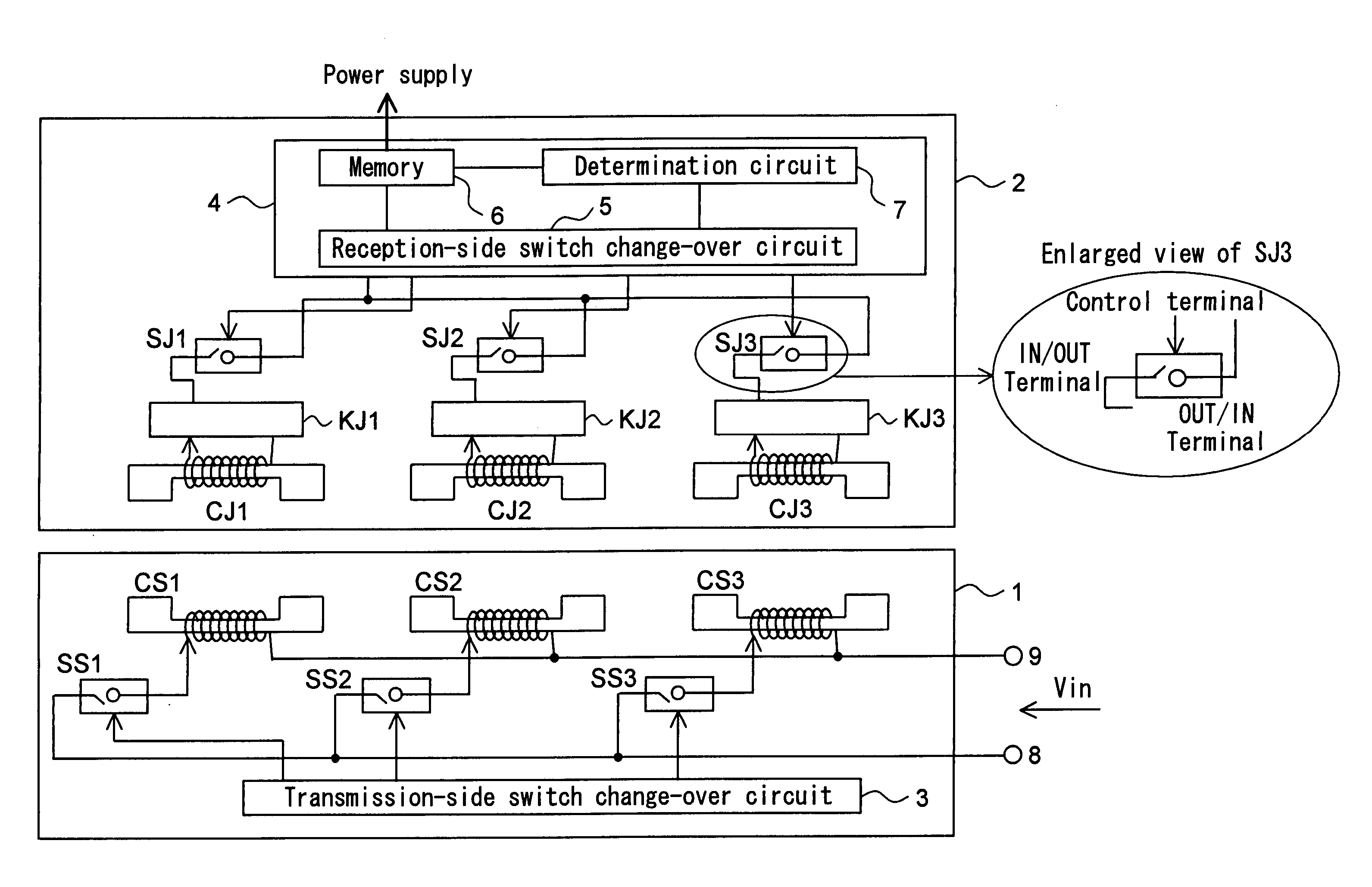
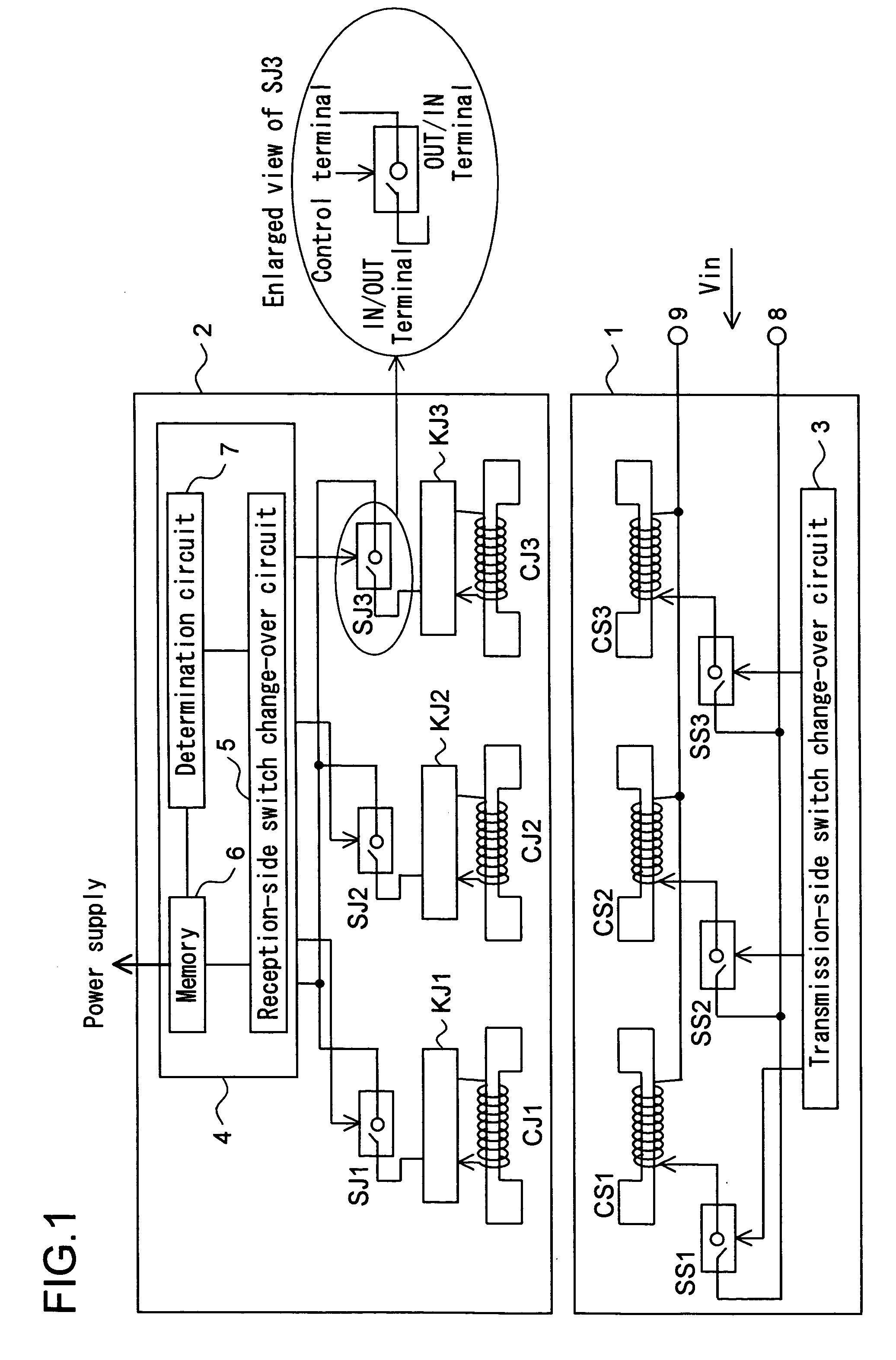
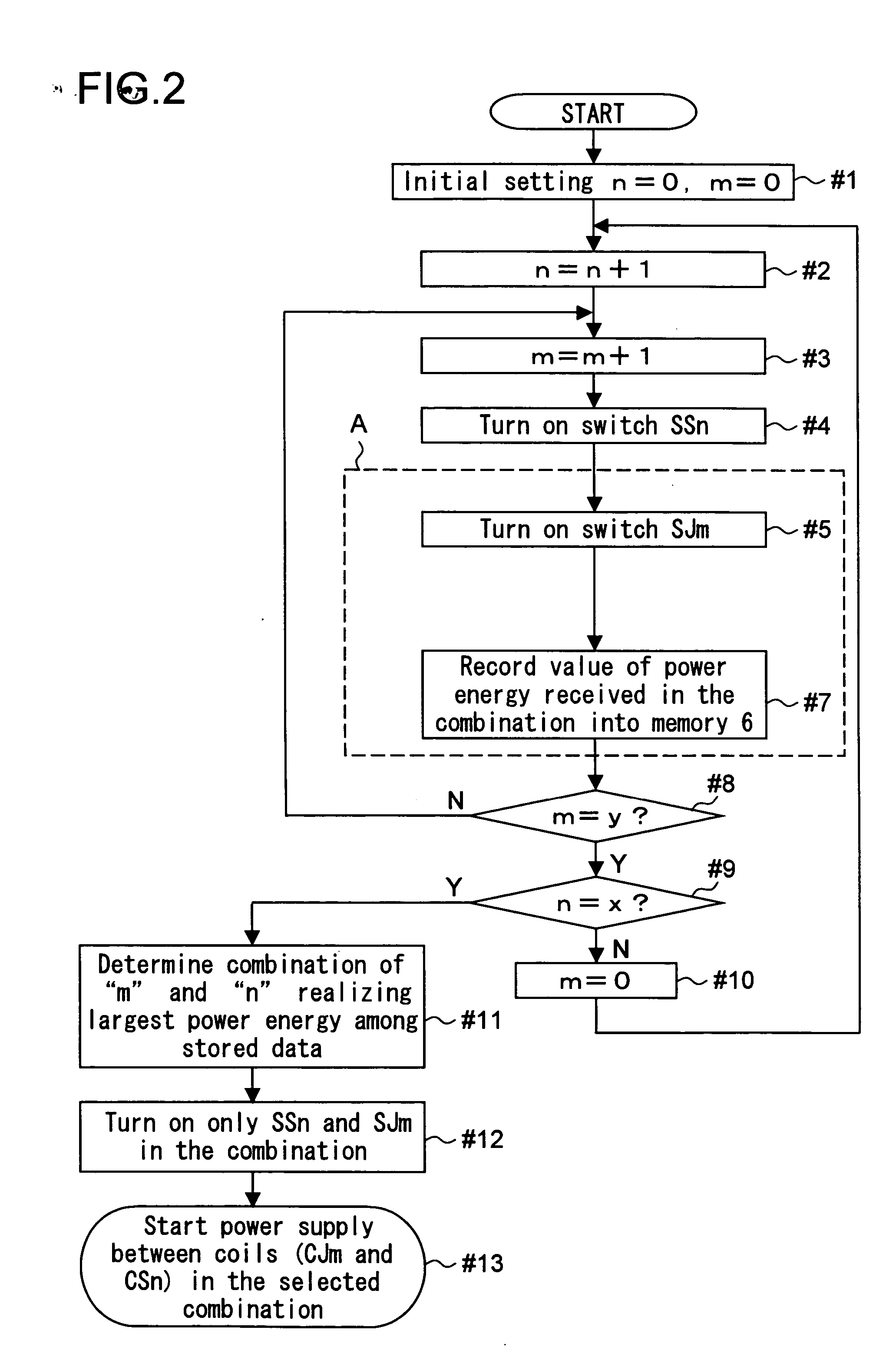
[0043] A first embodiment of a power supply system of the present invention will be described below with reference to FIGS. 1 to 3. FIG. 1 is a circuit configuration diagram of a power supply system according to the first embodiment and FIGS. 2 and 3 are flowcharts of operations. A power supply system of the first embodiment can supply power from a power transmitter (not shown) on the transmission side to a power receiver (not shown) on the reception side in an electrically non-contact manner and has a power transmission module 1 attached to the power transmitter and a power reception module 2 attached to the power receiver.

[0044] The power transmitter is a device for transmitting power to a power receiver. The power receiver is an electric device capable of charging driving power and is a mobile phone, a notebook-sized personal computer, a digital camera, an electric shaver, an electronic toy, and the like.

[0045] The power transmission module 1 has power transmission coils CS1, C...

second embodiment

[0072] First, a second embodiment of the power supply system of the present invention will be described with reference to FIG. 4. FIG. 4 is a circuit configuration diagram of the power supply system according to the second embodiment. The same reference numerals are designated to the same components as those in FIG. 1 and description of the operations and the like will not be repeated. The power supply system of the second embodiment is a power supply system capable of supplying power from a power transmitter (not shown) to a power receiver (not shown) in an electrically non-contact manner and has a power transmission module 21 attached to the power transmitter and a power reception module 22 attached to the power receiver. The operation of the power supply system of this embodiment is similar to that of the first embodiment described with reference to FIGS. 2 and 3.

[0073] The power transmission module 21 of the second embodiment is similar to the power transmission module 1 of the...

third embodiment

[0077] A third embodiment of the power supply system of the present invention will now be described with reference to FIG. 5. FIG. 5 is a circuit configuration diagram of the power supply system according to the third embodiment. The same reference numerals are designated to the same components in FIG. 1 and the description of operations and the like will not be repeated. The power supply system of the third embodiment is a power supply system which can supply power from a power transmitter (not shown) to a power receiver (not shown) in an electrically non-contact manner, and has a power transmission module 31 attached to the power transmitter and a power reception module 32 attached to the power receiver. The operation of the power supply system of the third embodiment is similar to that of the first embodiment described with reference to FIGS. 2 and 3.

[0078] The power transmission module 31 has a transmission-side switch change-over circuit 33, signal reception coils CIS1, CIS2 a...


PUM


Abstract

A power supply system capable of supplying power from a power transmitter to a power receiver in an electrically non-contact manner, in which a power transmission module is attached to the power transmitter and a power reception module is attached to the power receiver. The power transmission module has a plurality of transmission-side coils for transmitting power and a plurality of transmission-side switches for turning on / off operation of the transmission-side coils. The power reception module has a plurality of reception-side coils for receiving power, a plurality of reception-side switches for turning on / off operation of the reception-side coils and, further, has a determination circuit for performing control so as to operate any of the transmission-side coils and any of the reception-side coils in a combination realizing highest power transmission efficiency.

Description

[0001] This application is based on Japanese Patent Application No. 2003-339935 filed on Sep. 30, 2003, the contents of which are hereby incorporated by reference. BACKGROUND OF THE INVENTION [0002] 1. Field of the Invention [0003] The present invention relates to a system for supplying power to an electronic device or an electric device and, more particularly, to a power supply system suitable for an electronic device or an electric device of mobile devices such as a mobile phone, a notebook-sized personal computer, a digital camera, and an electronic toy. [0004] 2. Description of the Prior Art [0005]FIG. 12 shows a conventional configuration example of a non-contact power supply system using magnetic coupling. A power transmitter 100 has a primary coil 101 for transmitting power and a positioning projection 102, and a power receiver 103 has a secondary coil 104 for receiving power and a positioning recess 105. [0006] As shown in FIG. 12, the primary coil 101 and the secondary coil...

Claims


Application Information

Patent Timeline
IPC IPC(8): G05F1/70H02J7/00
CPCG05F1/70
Inventor AOKI, FUMIHIKO
Owner SHARP KK
Features
  • Generate Ideas
  • Intellectual Property
  • Life Sciences
  • Materials
  • Tech Scout
  • Unparalleled Data Quality
  • Higher Quality Content
  • 60% Fewer Hallucinations
Learn More