Method and apparatus for adapting antenna array using received perdetermined signal

a perdetermined signal and antenna array technology, applied in the field of mobile (or portable) cellular communication systems, can solve the problems of multipath fading, radio frequency signal transmitted from a sender (either a base station or mobile station) may encounter interference, fade or dropout of the received signal,

Inactive Publication Date: 2005-03-31
IPR LICENSING INC
View PDF41 Cites 85 Cited by
  • Summary
  • Abstract
  • Description
  • Claims
  • Application Information

AI Technical Summary

Benefits of technology

[0015] The intercell interference problem is exacerbated in Code Division Multiple Access (CDMA), since the stations in adjacent cells may typically be transmitting on the same frequency at the same time. For example, generally, two stations in adjacent cells operating at the same carrier frequency but transmitting to different base stations will interfere with each other if both signals are received at one of the base stations. One signal appears as noise relative to the other. The degree of interference and the receiver's ability to detect and demodulate the intended signal is also influenced by the power level at which the stations are operating. If one of the stations is situated at the edge of a cell, it transmits at a higher power level, relative to other units within its cell and the adjacent cell, to reach the intended base station. But, its signal is also received by the unintended base station, i.e., the base station in the adjacent cell. Depending on the relative power level of two same-carrier frequency signals received at the unintended base station, it may not be able to properly identify a signal transmitted from within its cell from the signal transmitted from the adjacent cell. What is needed is a way to reduce the station antenna's apparent field of view, which can have a marked effect on the operation of the forward link (base to the mobile station) by reducing the apparent number of interfering transmissions received at a base station. A similar improvement is needed for the reverse link, so that the transmitted signal power needed to achieve a particular receive signal quality can be reduced. BRIEF DESCRIPTION OF THE PRESENT INVENTION
[0021] The antenna apparatus thus acts as a beam former for transmission of signals from the mobile station and acts as a directional antenna for signals received by the mobile station. Through the use of an array of antenna elements, each having a programmable weight control component for forming the antenna beam as desired, the antenna apparatus increases the effective transmit power per bit transmitted. Thus, the number of active mobile stations in a cell may remain the same while the antenna apparatus of this invention increases data rates for each station beyond those achievable by prior art antennas. Alternatively, if data rates are maintained at a given rate, more mobile stations may become simultaneously active in a single cell using the antenna apparatus described herein. In either case, the capacity of a cell is increased, as measured by the sum total of data being communicated at any given time.
[0022] Forward link communications capacity can be increased as well, due to the directional reception capabilities of the antenna apparatus. Since the antenna apparatus is less susceptible to interference from adjacent cells, the forward link system capacity can be increased by adding more users or by increasing cell radius size.

Problems solved by technology

Various problems are inherent in prior art antennas used on mobile stations in wireless communications systems.
One such problem is called multipath fading.
In multipath fading, a radio frequency signal transmitted from a sender (either a base station or mobile station) may encounter interference on route to the intended receiver.
As a result, the original and reflected signals may partially cancel each other out (destructive interference), resulting in fading or dropouts in the received signal, hence the term multipath fading.
Single element antennas are highly susceptible to multipath fading.
A single element antenna has no way of determining the direction from which a transmitted signal is sent and cannot be tuned or attenuated to more accurately detect and receive a signal in any particular direction.
The dual element antenna described in the aforementioned reference is also susceptible to multipath fading, due to the symmetrical and opposing nature of the hemispherical lobes formed by the antenna pattern when the phase shifter is activated.
That is, if the original signal reflects from an object beyond or behind the intended receiver (with respect to the sender) and reflects back at the intended receiver from the opposite direction as the directly received signal, a phase difference in the two signals can create destructive interference due to multipath fading.
Another problem present is inter-cell interference.
Intercell interference occurs when a mobile station near the edge of one cell transmits a signal that crosses over the edge into a neighboring cell and interferes with communications taking place within the neighboring cell.
Typically, intercell interference occurs when similar frequencies are used for communications in neighboring cells.
The problem of intercell interference is compounded by the fact that stations near the edges of a cell typically use higher transmit powers so that the signals they transmit can be effectively received by the intended base station located at the cell center.
Consider that the signal from another mobile station located beyond or behind the intended receiver may be arrive at the base station at the same power level, representing additional interference.
The intercell interference problem is exacerbated in Code Division Multiple Access (CDMA), since the stations in adjacent cells may typically be transmitting on the same frequency at the same time.
For example, generally, two stations in adjacent cells operating at the same carrier frequency but transmitting to different base stations will interfere with each other if both signals are received at one of the base stations.
Depending on the relative power level of two same-carrier frequency signals received at the unintended base station, it may not be able to properly identify a signal transmitted from within its cell from the signal transmitted from the adjacent cell.

Method used


Image

  • Method and apparatus for adapting antenna array using received perdetermined signal
  • Method and apparatus for adapting antenna array using received perdetermined signal
  • Method and apparatus for adapting antenna array using received perdetermined signal

Examples


Embodiment Construction

[0031] A description of preferred embodiments of the invention follows.

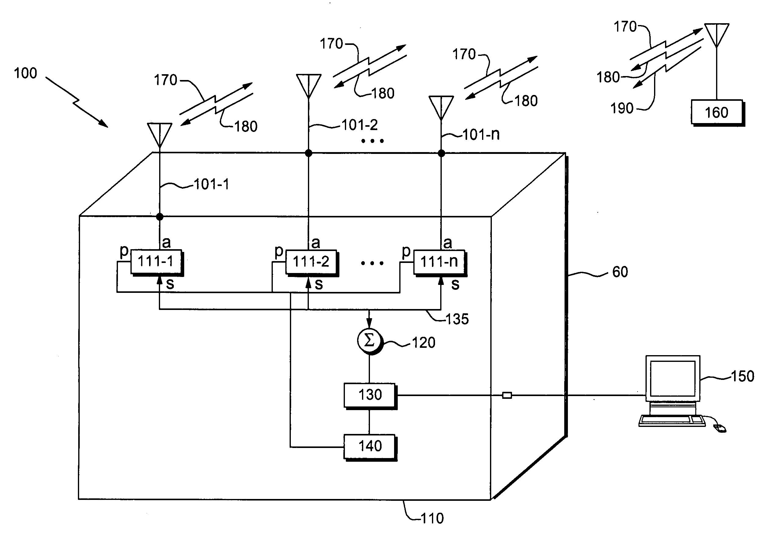
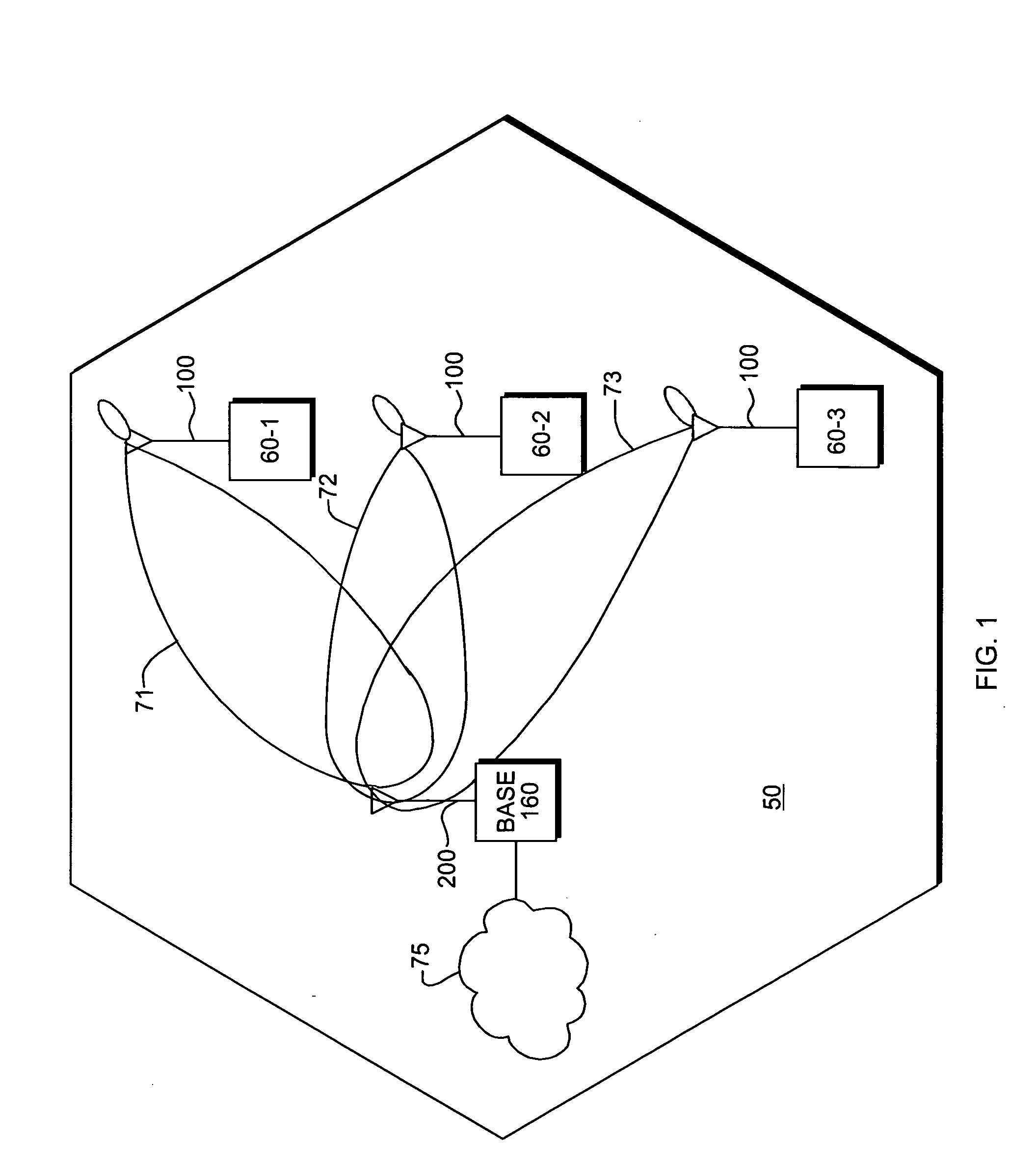
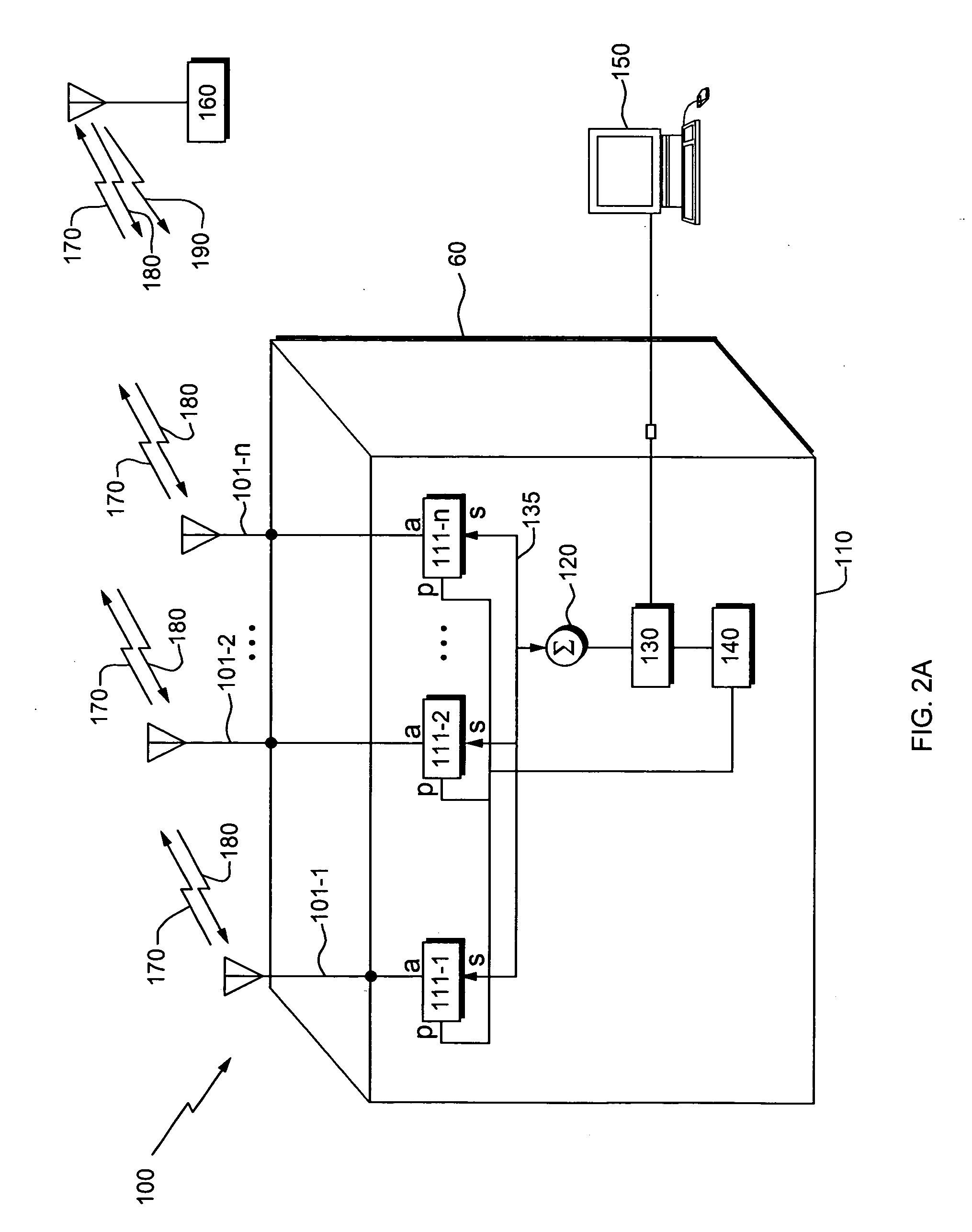
[0032]FIG. 1 illustrates a typical wireless communication system such as a CDMA cellular communication system. The cell 50 represents a physical area in which mobile stations 60-1 through 60-3 communicate with a centrally located base station 160. One or more mobile stations 60 are equipped with an antenna 100 configured according to the present invention. The mobile stations 60 are provided with wireless data and / or voice services by the system operator and can connect devices such as, for example, laptop computers, portable computers, personal digital assistants (PDAs) or the like through base station 160 to a network 75, which can be the public switched telephone network (PSTN), a packet switched computer network, such as the Internet, a public data network or a private intranet. The base station 160 can communicate with the network 75 over any number of different available communications protocols such as pr...


PUM


Abstract

An antenna apparatus that can increase capacity in a wireless communication system is disclosed. The antenna operates in conjunction with a station and comprises a plurality of antenna elements, each coupled to a respective weight control component to provide a weight to the signal transmitted from (or received by) each element. The weight for each antenna element is adjusted to achieve optimum reception during, for example, an idle mode when a pilot signal is received. The antenna array creates a beam former for signals to be transmitted from the mobile station, and a directional receiving array to more optimally detect and receive signals transmitted from the base station. By directionally receiving and transmitting signals, multipath fading and intercell interference are greatly reduced. The weights are adjusted in a coarse and a fine mode. In the coarse mode all the weight control components are jointly adjusted or changed so that the antenna beam scans through a predetermined sector of a circle until a signal quality metric of the received signal is optimized. The coarse adjustment mode is followed by a fine adjustment mode during which the weights of are independently adjusted to further optimize the signal quality metric.

Description

RELATED APPLICATIONS [0001] This application is a continuation-in-part of U.S. patent application Ser. No. 09 / 776,558 filed Feb. 2, 2001 entitled “Method and Apparatus For Adapting Antenna Array To Reduce Adaptation Time While Increasing Array Performance,” which is itself a continuation-in-part of U.S. patent application Ser. No. 09 / 579,084 filed May 25, 2000 entitled “Adaptive Antenna For Use In Same Frequency Networks,” which is a divisional application of U.S. patent application Ser. No. 09 / 210,117 filed Dec. 11, 1998, now U.S. Issued U.S. Pat. No. 6,100,843, entitled “Adaptive Antenna for use in Same Frequency Networks,” which is a continuation application of U.S. patent application Ser. No. 09 / 157,736 filed Sep. 21, 1998 entitled “Method and Apparatus Providing an Adaptive Antenna For Use in Same Frequency Networks”. The entire teachings of all of the above applications are incorporated herein by reference. BACKGROUND OF THE INVENTION [0002] This invention relates to mobile (o...

Claims


Application Information

Patent Timeline
Patent Type & Authority Applications(United States)
IPC IPC(8): H01Q1/24H01Q3/26H01Q3/28H01Q3/36H04B7/06H04B7/08
CPCH01Q1/246H01Q3/2605H04B7/086H01Q3/36H04B7/0617H01Q3/28
Inventor REGNIER, JOHN A.PROCTOR, JAMES A. JR.LYNCH, MICHAEL J.GORSUCH, THOMAS E.
Owner IPR LICENSING INC
Why Eureka
Try Eureka