Multiple-frequency common antenna

a common antenna and multi-frequency technology, applied in the direction of resonant antennas, antenna earthings, elongated active elements, etc., can solve the problems of complex interference of direct wave radiated directly from the antenna, difficult to provide a space for antenna installation, and difficult to install a plurality of antennas in the limited space within the vehicl

Inactive Publication Date: 2005-03-31
TELEDYNE SCI & IMAGING +1
View PDF11 Cites 31 Cited by
  • Summary
  • Abstract
  • Description
  • Claims
  • Application Information

AI Technical Summary

Benefits of technology

[0016] It is therefore an object of the present invention to provide a common or shared antenna which can control re-radiation of electromagnetic wave from the end part of a ground plane. Moreover, it is also an object of the present invention to provide an antenna which resonates in a plurality of frequency bands, realizes power feeding with only one power feeding line and controls re-radiation of the electromagnetic wave from the end part of the ground plane.
[0017] According to the present invention, a multiple-frequency common antenna comprises a substrate sheet having a band gap for prohibiting propagation of an electromagnetic wave on a surface in a particular frequency band. It also comprises a first antenna that resonates in a first frequency band within the band gap provided on the surface of the substrate sheet, and a second antenna that resonates in a second frequency band out of the band gap. Thus, the first antenna and the second antenna can operate in the different frequency bands. Further, the electromagnetic wave radiated from the first antenna does not flow as the surface current due to the band gap of the substrate, re-radiation of the electromagnetic wave from the periphery of the substrate and hence the directivity of the first antenna is not changed.

Problems solved by technology

(1) It is difficult to install a plurality of antennas in the limited space within a vehicle.
Particularly, since air-conditioner, various meters, air-bag apparatus, moreover, information terminal devices such as audio device and navigation device are provided within the instrument panel, it is very difficult to provide a space for installation of antennas.
The reflected waves from these metallic members and the direct wave radiated directly from the antenna are complicatedly interfere with each other and thereby many dead-band directions of radio waves.
That is, many null points are formed and the antenna characteristics are worsened.
However, these multiple-frequency antennas of the prior art cannot solve the above problem (3).
The problem (3) arises, as is well known, when the direct wave radiated from a radiation element of the antenna interfere with the wave generated when a surface current flowing on the ground plane of the antenna is re-radiated from the end part of the ground plane.
However, this prior art cannot solve the above problems (1) and (2).

Method used


Image

  • Multiple-frequency common antenna
  • Multiple-frequency common antenna
  • Multiple-frequency common antenna

Examples


first embodiment

[0075] (First Embodiment)

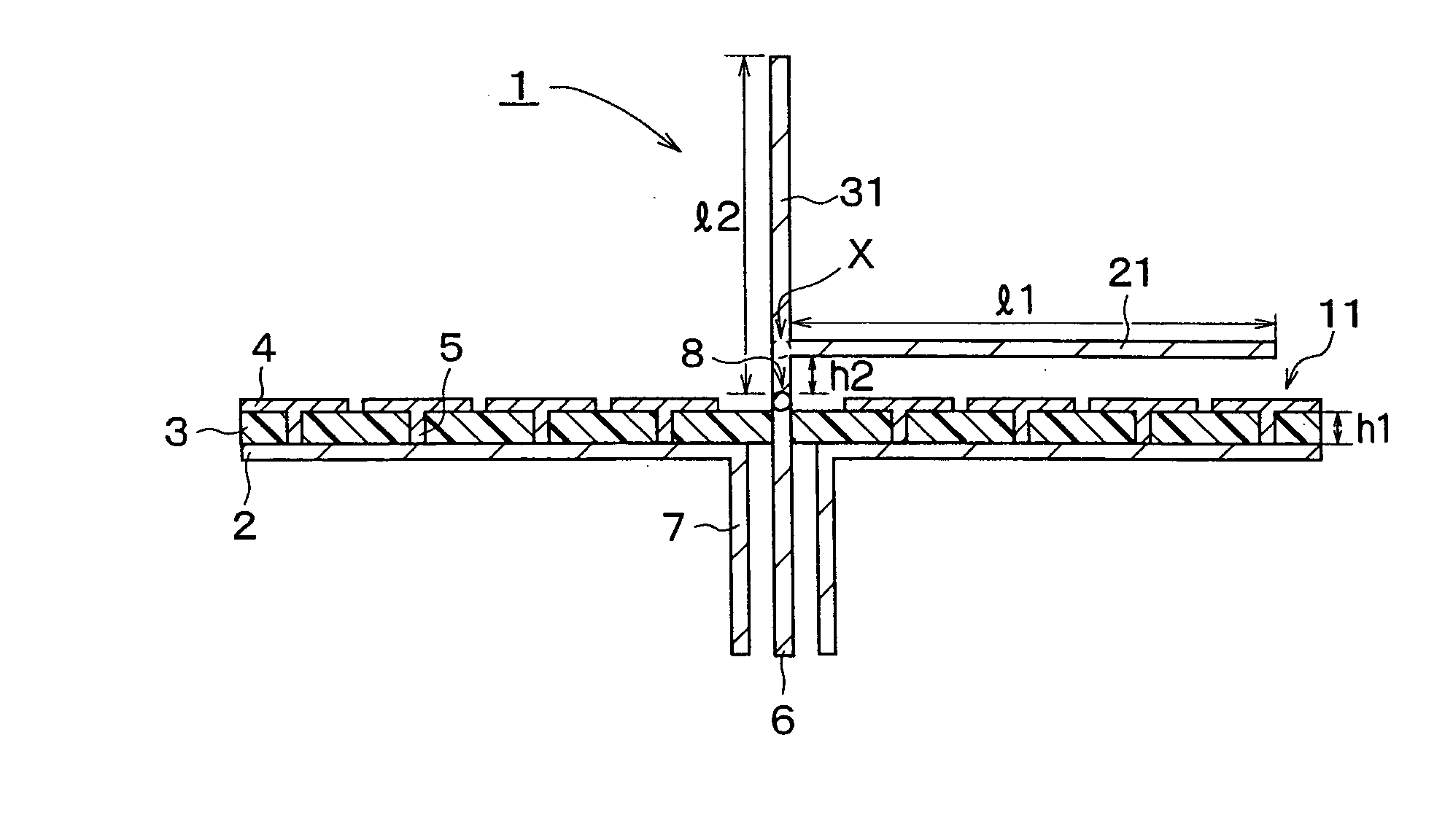
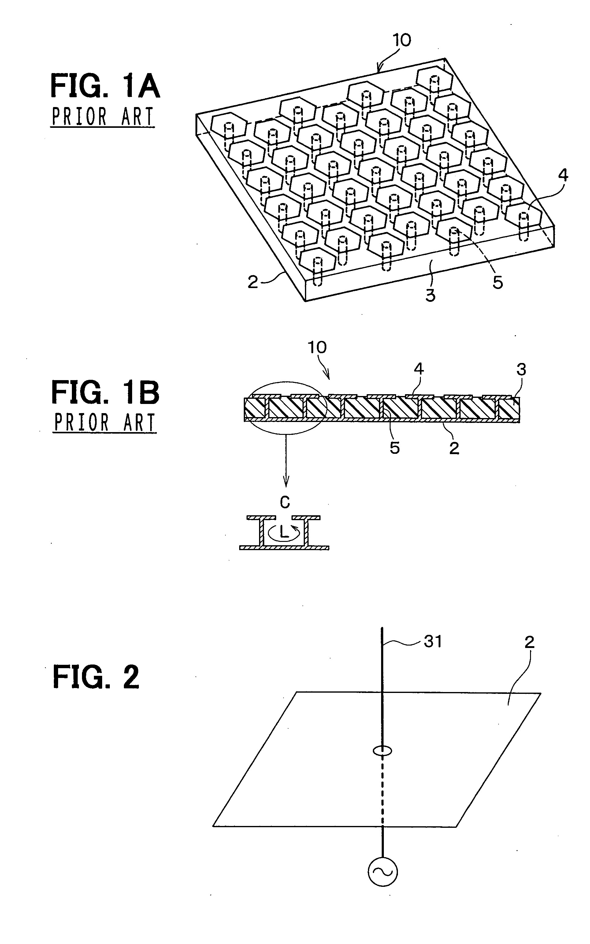
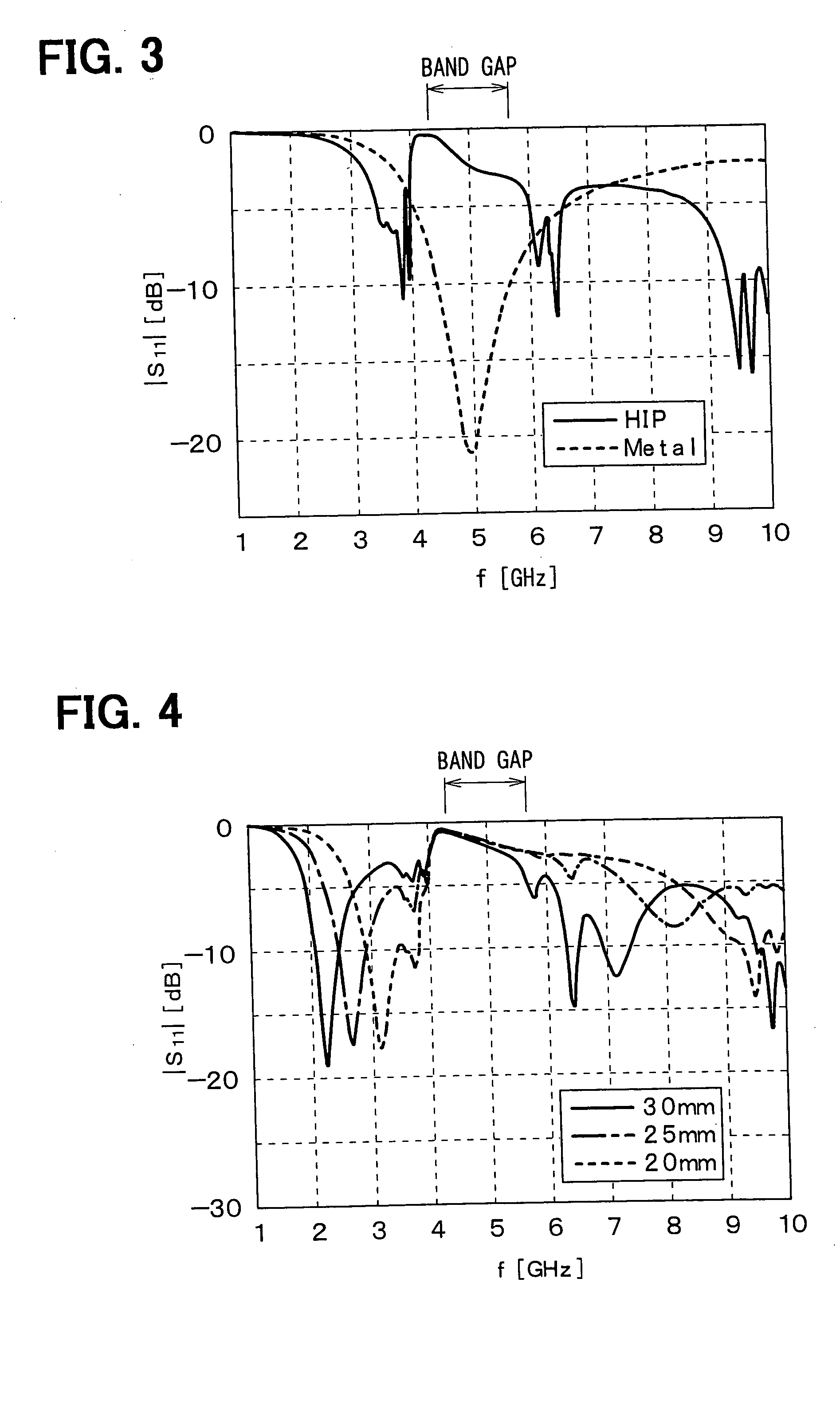
[0076] A perspective view of a first embodiment of the present invention is shown in FIG. 11, while a cross-sectional view of the same is shown in FIG. 12. An HIP 11 used as a substrate sheet of a multiple-frequency common antenna 1 of the first embodiment is formed by disposing, as shown in FIG. 13, small hexagonal metal plates 4 in the pitch d1 of 7 mm and the gap between the plates d2 of 0.15 mm on a dielectric material layer 3 in the dielectric coefficient of 2.6 and the thickness h1 of 3.2 mm. These small metal plates 4 are connected with a metal plate forming the rear surface of the HIP 11 using through-holes 5 as the linear metal bars in the diameter d3 of 0.8 mm. In the structure explained above, the resonant frequency of the HIP 11 in this embodiment is set to 5 GHz. As the dielectric material layer 3, an air layer or a dielectric material substance other than the air may be used. As will be explained later, the geometry of HIP must be determined co...

second embodiment

[0083] (Second Embodiment)

[0084]FIG. 18 shows a perspective view of the multiple-frequency common antenna according to the second embodiment of the present invention. In FIG. 18 and the subsequent figures, the surface including the small metal plates 4 of the HIP are indicated as the hatched areas.

[0085] The multiple-frequency common antenna according to the second embodiment is provided, at the outer peripheral portion of a first substrate sheet 11, with the HIP as the first substrate sheet 11 which has also been used as the substrate sheet of the multiple-frequency common antenna in the first embodiment and the HIP as a second substrate sheet 12 in which the second frequency band including the resonant frequency of 2.46 GHz of the monopole antenna as the second antenna is defined as the frequency band from the band gap. However, the first frequency band and the second frequency band are set not to overlap with each other.

[0086] The band gap of the HIP used as the substrate sheet...


PUM


Abstract

A multiple-frequency common antenna has a first substrate sheet and a second substrate sheet respectively structured by an HIP consisting of a metal plate, small metal plates disposed in two dimensions and linear metal bars connecting these elements. The antenna restricts propagation of surface currents of the first and second frequency bands which are not overlapping with each other. An inverse L-shape antenna and a monopole antenna which are fed with a center conductor and an external conductor of the coaxial line respectively operate as the antenna on the first substrate sheet in the first frequency band and second frequency band. The second substrate sheet does not propagate the radiated wave of the monopole antenna, thereby avoiding unwanted re-radiation.

Description

FIELD OF THE INVENTION [0001] The present invention relates to a multiple-frequency common antenna which resonates at a plurality of frequencies and a communication apparatus utilizing the same multiple-frequency antenna. BACKGROUND OF THE INVENTION [0002] In recent years, the number of mobile radio terminals to be loaded to a mobile station, particularly, a vehicle station is increased with rapid progress thereof toward high level information systems. The terminals may be a GPS (Global Positioning System) receiver, mobile telephone system and ETC (electronic toll collection) communication system. In these radio terminals, different frequencies are respectively used to eliminate interference. Therefore, the radio terminals are required to have respective antennas which operate, that is, resonate in different frequencies. [0003] Moreover, it is desirable that these antennas are installed at the area near the instrument panel of vehicle or on the vehicle chassis in which rather excell...

Claims


Application Information

Patent Timeline
Patent Type & Authority Applications(United States)
IPC IPC(8): H01Q15/14H01Q5/10H01Q9/30H01Q9/42H01Q9/44H01Q13/08H01Q15/00H01Q19/10
CPCH01Q9/42H01Q15/008H01Q9/44
Inventor TANAKA, MAKOTOMATSUGATANI, KAZUOKIXIN, HAO
Owner TELEDYNE SCI & IMAGING
Why Eureka
Try Eureka