System for correcting optical center linked with lens shift

a technology of optical center and lens shift, applied in the field of geometrical correction, can solve the problems of difficult to predict what, lack of functional relation of correction geometry,

Inactive Publication Date: 2005-03-31
NEC VIEWTECH
View PDF6 Cites 23 Cited by
  • Summary
  • Abstract
  • Description
  • Claims
  • Application Information

AI Technical Summary

Benefits of technology

[0008] As described above, the present invention allows automatically detecting the displacement of the optical center through linkage with the shift magnitude of the lens by predicting in advance the displacement of the optical center in dependence on a shift magnitude of the lens, thereby correcting a displacement of the optical center automatically on the basis of the detected displacement. As a result, it is feasible to move a screen image projected on a screen by shifting the lens in the vertical or horizontal direction without changing the position of the projector. Furthermore, while it is envisaged that the data on the position of the optical center and the data on the centrally aligned location of the lens (the reference location of the lens) vary to some extent with each projector,.appropriate correction is feasible even if the variation exists, because these data can be stored in the projector or the like at the time of production.

Problems solved by technology

In other words, the conventional method of correcting the geometry lacks a functional relation between the magnitudes of the lens shift and displacement of the optical center and consequently it has been difficult to predict what lens shift causes what displacement in the optical center.

Method used


Image

  • System for correcting optical center linked with lens shift
  • System for correcting optical center linked with lens shift
  • System for correcting optical center linked with lens shift

Examples


first embodiment

[0017] Explanation is next presented regarding the present invention referring to FIG. 1 through FIG. 3.

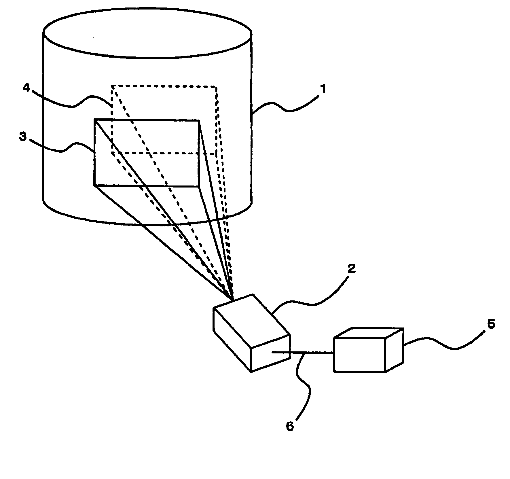
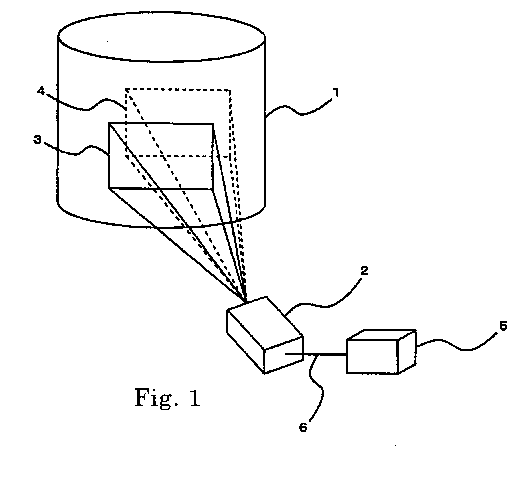
[0018]FIG. 1 is a block diagram of the optical-center correction system of the first embodiment according to the present invention. The optical-center correction system comprises curved screen 1 (or a screen that needs some extent of geometrical correction such as a spherical surface, a joining edge portion of walls and a curtain as shown in FIG. 7 and FIG. 8, other than a planar surface); projector 2 for projecting an image having the lens-shift function; and computer 5 for arithmetic processing (hereinafter referred to as PC). Projector 2 and PC 5 are connected through communication cable 6 having a capability of two-way communication, allowing exchange of information with each other.

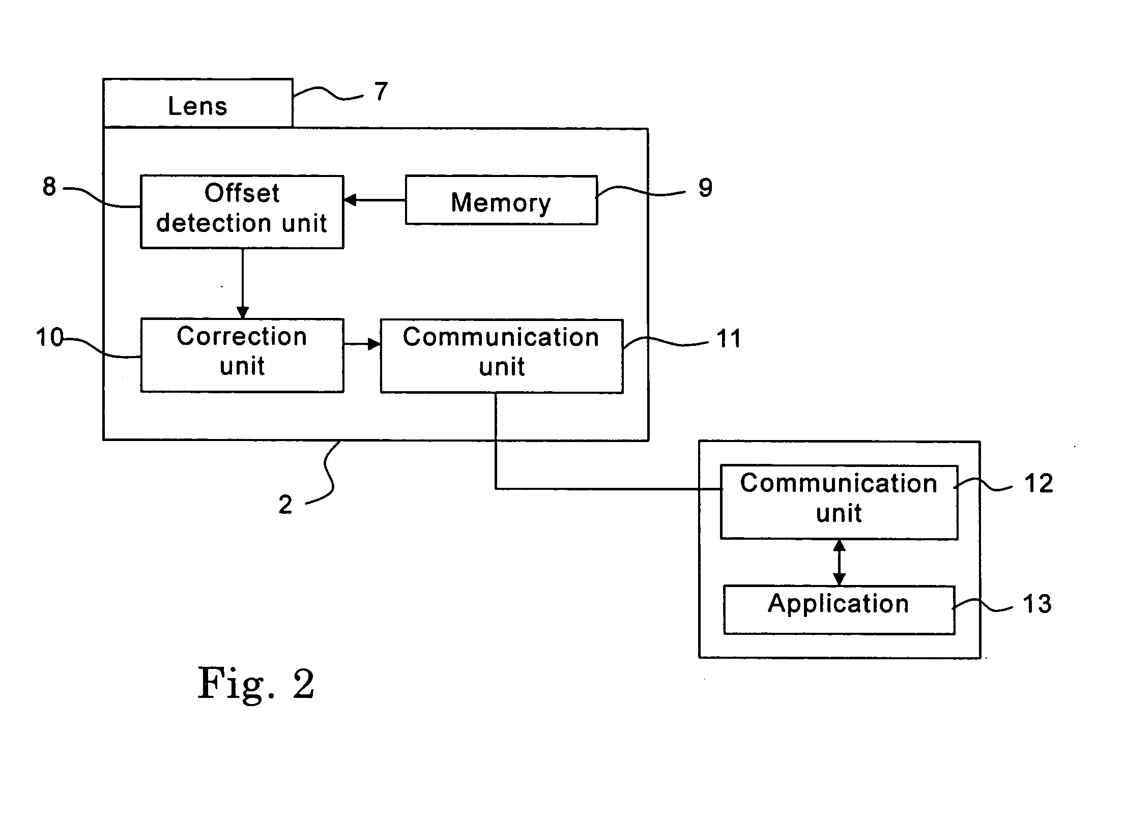
[0019]FIG. 2 is a block diagram of the projector. Projector 2 comprises lens 7, offset detection unit 8, memory 9, correction unit 10 and communication unit 11. PC 5 comprises communication unit 12...


PUM

PropertyMeasurementUnit
displacementaaaaaaaaaa
optical centeraaaaaaaaaa
travel distanceaaaaaaaaaa

Abstract

A system for correcting an optical center is provided with: a lens control unit for shifting a lens in vertical and horizontal directions; an offset detection unit for detecting a displacement of the optical center with respect to a screen on a basis of a magnitude of a shift of the lens effected by the lens control unit; a memory unit for storing in advance data on the centrally aligned location of the lens and also data on the positions of the optical center effected by lens shifts; and a correction unit for linking the displacement of the optical center detected by the offset detection unit with the data on the centrally aligned location of the lens and the data on the position of the optical center effected by the lens shift stored in the memory unit to correct the displacement of the optical center.

Description

BACKGROUND OF THE INVENTION [0001] 1. Field of the invention [0002] The present invention relates to a system for geometrical correction and particularly to an optical-center correcting system for automatically correcting the position of an optical center through linkage with a lens shift. [0003] 2. Description of the Related Art [0004] When it happens that the optical center is displaced from the center of the lens due to a lens shift, a conventional way of correcting geometry has required correcting the displacement of the optical center first and then correcting a distortion in the geometry, in order to properly make a distortion correction. In other words, the conventional method of correcting the geometry lacks a functional relation between the magnitudes of the lens shift and displacement of the optical center and consequently it has been difficult to predict what lens shift causes what displacement in the optical center. For this reason, when the optical center of the project...

Claims


Application Information

Patent Timeline
Patent Type & Authority Applications(United States)
IPC IPC(8): G03B21/00G02B7/00G02B27/00G03B5/06H04N5/74
CPCG02B7/005H04N5/74G02B27/0025
Inventor MORIWAKI, DAISUKEKOMATSU, YOSHIHARU
Owner NEC VIEWTECH
Why Eureka
Try Eureka