Variable polarization independent optical power splitter

a technology of optical power splitter and variable polarization, which is applied in the direction of optical elements, instruments, optical radiation measurement, etc., can solve the problems that the beam splitter described in any of the aforementioned patents is not suitabl

Inactive Publication Date: 2005-03-31
ACCELINK TECHNOLOGIES CO LTD
View PDF7 Cites 18 Cited by
  • Summary
  • Abstract
  • Description
  • Claims
  • Application Information

AI Technical Summary

Benefits of technology

It is an objective of the present invention to provide a variable polarization independent optical power splitter, and a method for splitting the power of an input light beam of an arbitrary polarizat

Problems solved by technology

However, for applications where the polarization state of the light beam is not known, and where a variable power split ratio is required, the beam splitters described in any of the aforementioned patents are not suitable: either the power split ratio is fixed, or the splitter relies

Method used


Image

  • Variable polarization independent optical power splitter
  • Variable polarization independent optical power splitter
  • Variable polarization independent optical power splitter

Examples


first embodiment 100

First Embodiment 100 of the Invention

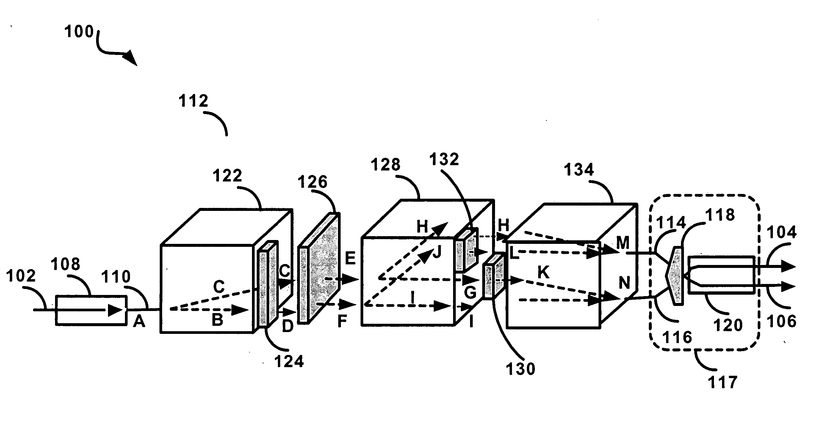
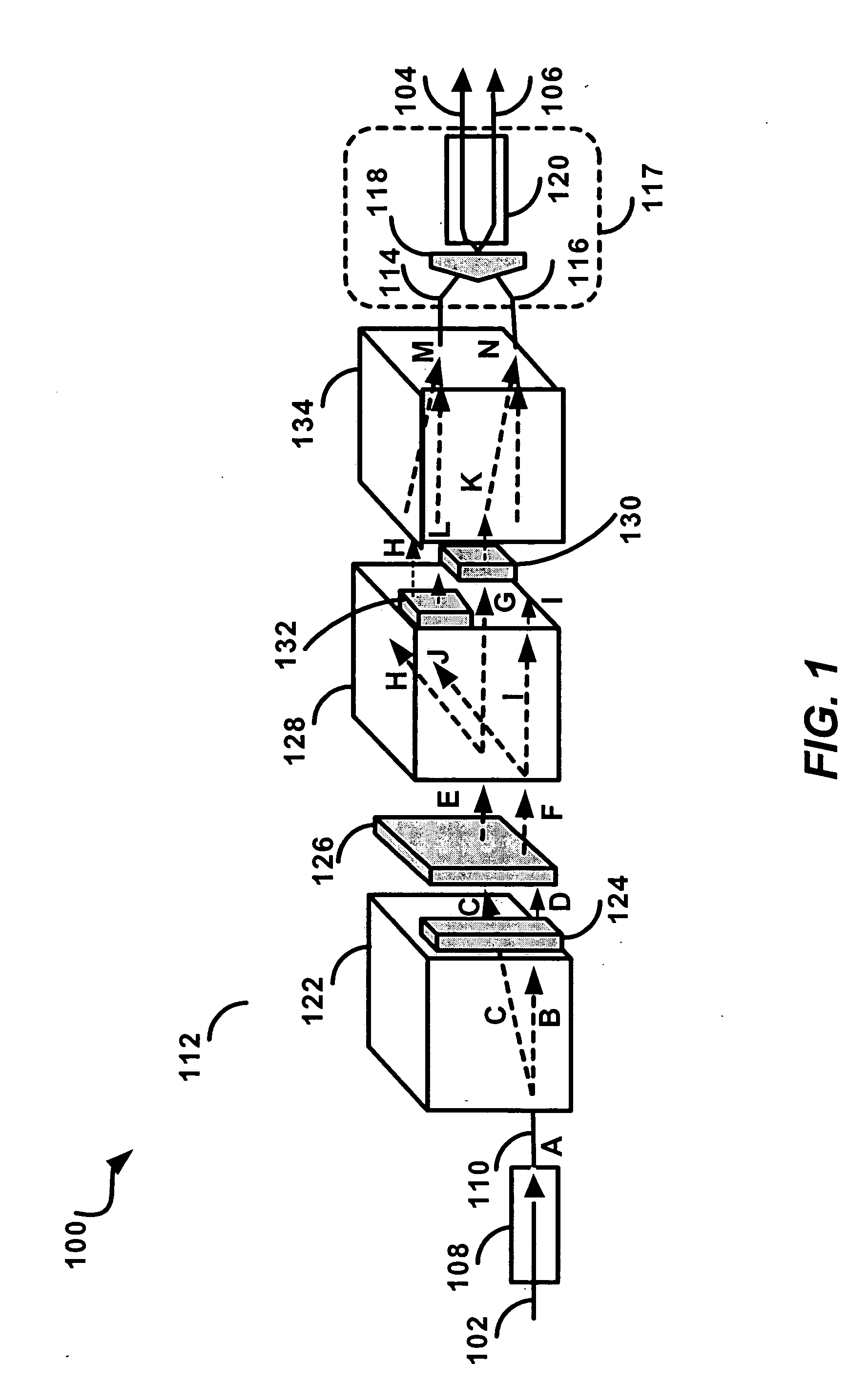
FIG. 1 is an illustration of a first embodiment 100 of the invention, showing a 1:2 optical splitter, having an optical input 102 and two optical outputs 104 and 106. The optical input fiber 102 is coupled to a standard collimator 108. The output of the standard collimator 108 is a straight light beam coupled to an input 110 of a first implementation of a variable polarization independent optical power splitter 112. The variable polarization independent optical power splitter 112 has two outputs, 114 and 116, which are coupled through an output unit 117 comprising a roof prism 118 and dual fiber collimator 120, to the optical output fibers 104 and 106 respectively.

The variable polarization independent optical power splitter 112 comprises; a first polarization separator 122 (implemented by a birefringent displacer); a first fixed polarization rotator 124 (implemented by a half-wave plate); a variable polarization rotator 126 (implemented by a...

second embodiment 200

Second Embodiment 200 of the Invention

FIG. 3 is an illustration of a second embodiment 200 of the invention, showing a 1:2 optical splitter. The second embodiment 200 of the invention is similar to the first embodiment 100, comprising many of the same elements, identified by the same reference numbers, incremented by 100.

second embodiment

the invention 200 comprises a second implementation of a variable polarization independent optical power splitter 212 which is similar to the first implementation 112 with the following exceptions: instead of the second polarization separator 128 implemented by a second birefringent displacer (as in the first embodiment of the invention), the second embodiment includes a second polarization separator 228 implemented by a Wollaston prism; and an output unit 217 comprising a dual fiber collimator 220, but no roof prism (118 in the first embodiment) since it is not required.

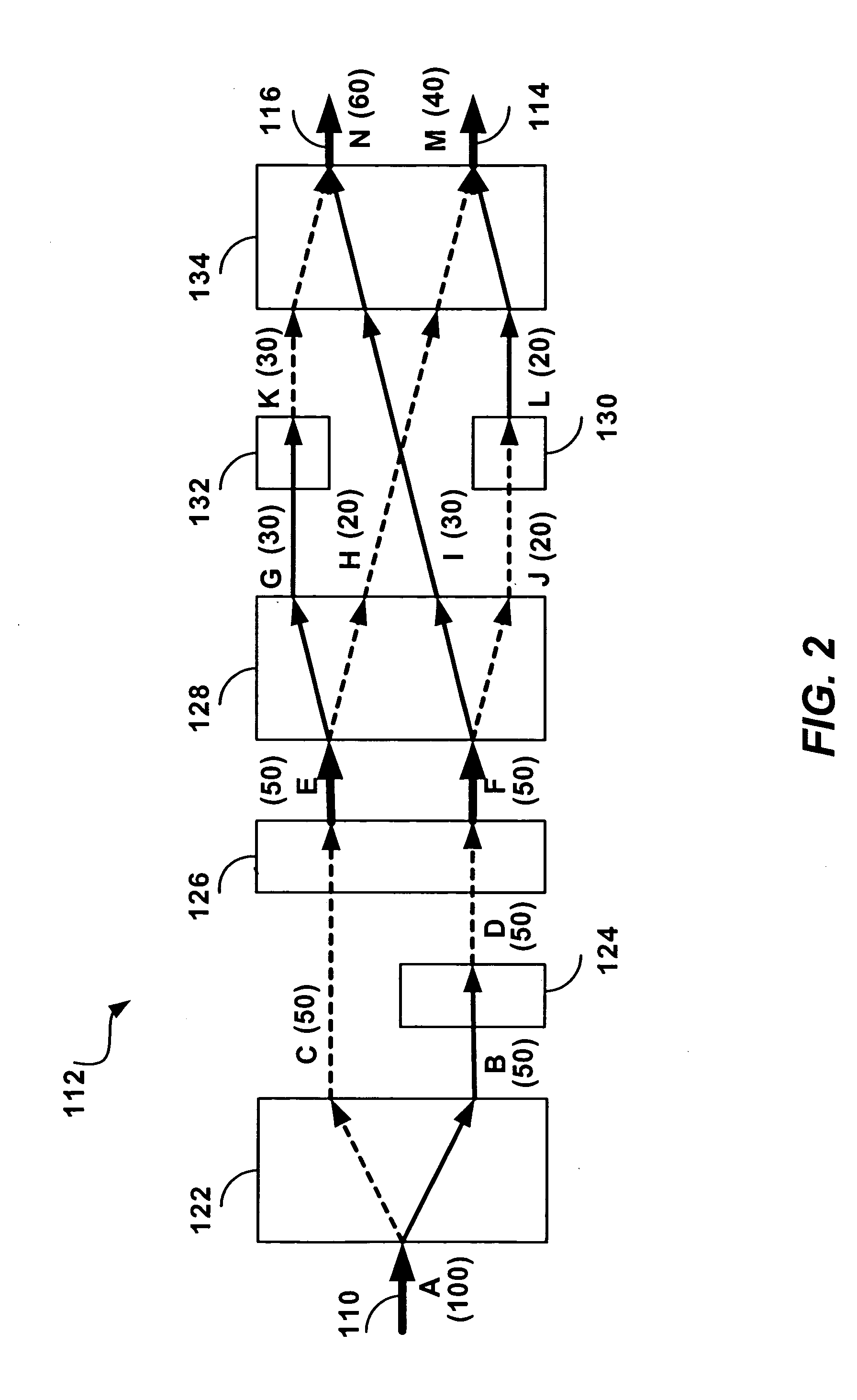
The three-dimensional diagram of the second embodiment of the invention 200, shown in FIG. 3, is a conceptual and approximate illustration of the spatial disposition of the optical components and light beams. A schematic diagram of the variable polarization independent optical power splitter 212 is shown in FIG. 4, using the same reference labels, and illustrating logically the passage of the light beams through th...


PUM


Abstract

An optical power splitter for variably splitting an arbitrarily polarized light beam into two or more light beams, is disclosed. An input light beam “A” is received and split it into two output light beams “M” and “N” where the optical power ratio of the two output light beams “M” and “N” is adjusted to a desired ratio by controlling a variable polarization rotator (liquid crystal unit). The polarization components “P” and “S” of the input light beam “A” are separated in a first polarization separator (birefringent displacer), then processed through the variable polarization rotator and a second polarization separator. Finally the processed optical components are recombined in a polarization combiner so as to constitute the desired output light beams “M” and “N” having the desired optical power ratio “R”. The polarization independence of the power split is thus achieved through the stratagem of processing the “P” and “S” polarized components of the input light beam “A” separately—resulting in four light beams “H”, “I”, “L” and “K” which appropriately combined in the polarization combiner yield the output light beams “M” and “N”. A number of embodiments are disclosed with different optical technology in the second polarization separator (Wollaston prism) and the variable polarization rotator (mechanically or electro-mechanically adjusted wave plate), with optical deflection means (for physical compactness) and photo detectors (for optical power monitoring), as well as an embodiment for a four-way split.

Description

FIELD OF THE INVENTION The invention relates to optical power splitters, specifically optical power splitters that permit a variable adjustment of the ratio of the split, and where the split is independent of the polarization of the incident beam. BACKGROUD OF THE INVENTION Optical power splitters are required in many types of optical communications networks, such as long haul networks, metropolitan networks, and access networks, as well as in optical multiplexers and switches of such networks. Fused fiber couplers can be used as optical power splitters, and have been known for many years as described, for example in U.S. Pat. Nos. 4,666,234, 5,064,267, 6,031,948, and 6,643,433, and have also been used within more complex optical systems, see e.g. U.S. Pat. No. 6,031,948. In modern fiber optic telecommunications, much reliance is being placed on the state of polarization of light signals. Typically the polarization of the signal is used to help direct the signal along the fiber ...

Claims


Application Information

Patent Timeline
IPC IPC(8): G01B9/02G02B6/27G02B6/34G02B27/10G02B27/28G02F1/00G02F1/01G02F1/03H04J14/06
CPCG02B6/272G02B6/2766G02B6/2773G02B6/4215H04J14/06G02F1/0136G02F1/0311G02F1/0322G02B27/286
Inventor LIU, WENWU, KEYULUO, YONG
Owner ACCELINK TECHNOLOGIES CO LTD
Why Eureka
Try Eureka