

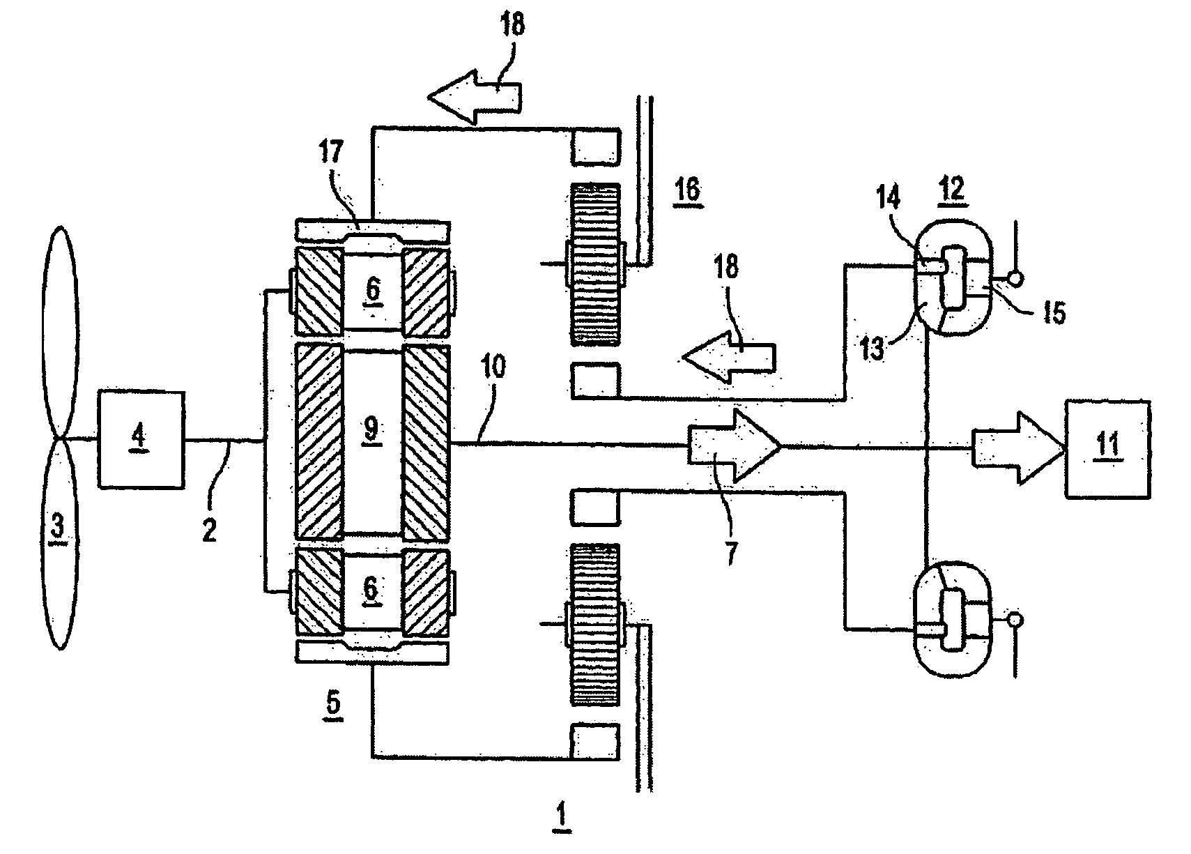
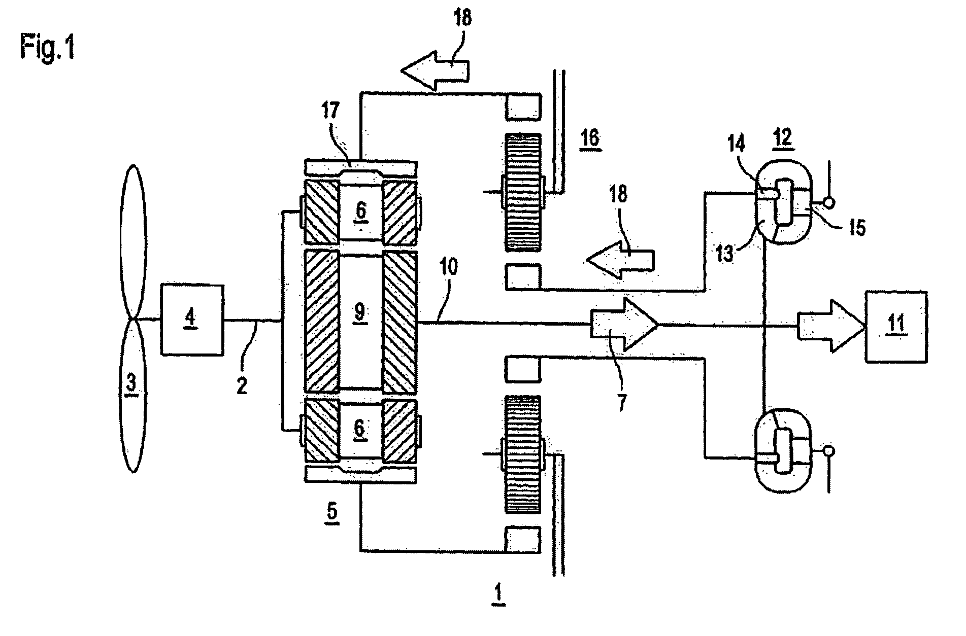
Drive train for the transmission of a variable power
a technology of variable power and drive train, which is applied in the direction of fluid gearing, differential gearing, engine fuction, etc., can solve the problems of system not being free of feedback for the power network, unable to achieve the effect of reducing the jerk in the drive train, and improving the control characteristic of the system
- Summary
- Abstract
- Description
- Claims
- Application Information
AI Technical Summary
Benefits of technology
Problems solved by technology
Method used
Image

Examples
Embodiment Construction
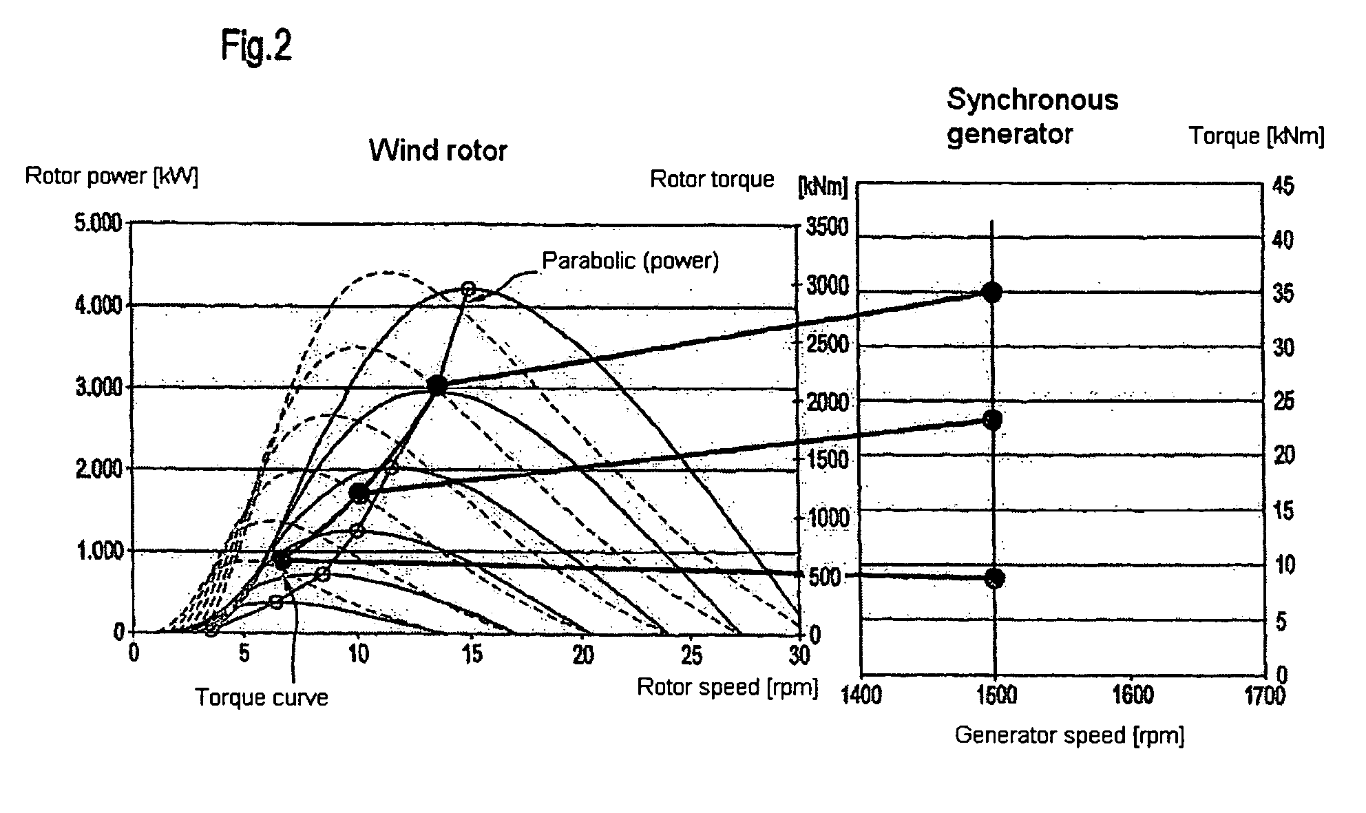
[0040]The rotor power pR of a wind power station is related in approximation to the wind speed vW as follows:
[0041]pR=k cP(νW, ωR, β)ν3w
[0042]Here, k comprises various constants, such as, for example, the blade geometry and the density of the air. Furthermore, cP represents the performance coefficient, which, in turn, as shown, depends on the wind speed vW, the rotor speed ωR, and the pitch angle β. This performance coefficient is characterized by a global maximum, which shifts to higher rotor speeds ωR as the wind speed vW increases.
[0043]FIG. 2 shows this relation by way of the depiction of groups of solid curves for the effective power of the rotor and of groups of dashed curves for the torque of a wind power station that is input by the rotor, taking into consideration various wind speeds, whereby the individual curves in the groups of curves are each assigned, by way of example, to a wind speed. Characteristic is the shift of the optimal rotor speed to higher values at increas...
PUM
 Abstract
Description
Claims
Application Information