Multimode electromechanical variable speed transmission apparatus and method of control

a technology of electromechanical variable speed and transmission apparatus, which is applied in the direction of battery/fuel cell control arrangement, battery/cell propulsion, etc., can solve the problems of reducing power transmission efficiency, limiting the effective operating speed ratio of the transmission, and not being suitable for all electric drives, so as to improve fuel efficiency and performance characteristics, avoid internal power circulation, and improve power transmission efficiency

Inactive Publication Date: 2015-10-15
AI XIAOLIN +3
View PDF0 Cites 26 Cited by
  • Summary
  • Abstract
  • Description
  • Claims
  • Application Information

AI Technical Summary

Benefits of technology

[0005]One of the objectives of current invention is to overcome the aforementioned drawbacks of the prior art by providing a novel multi-mode electro-mechanical variable speed transmissions with much improved fuel efficiency and performance characteristics. The transmission can operate under at least two different power splitting modes, offering higher power transmission efficiency by avoiding internal power circulation. The transmission is capable of providing continuously variable output to input speed ratio and independent power regulation, which significantly extends the operational speed ratio range. The transmission may also be operated in two pure electric modes with much improved acceleration performance and in two fixed speed ratio modes with maximum transmission efficiency.

Problems solved by technology

One of the power paths sees more power than that is transmitted through the transmission, which reduces power transmission efficiency.
This, to a large extent, constrains the effective operating speed ratio of the transmission.
This makes THS not suitable for all electric drive in power demanding applications.

Method used


Image

  • Multimode electromechanical variable speed transmission apparatus and method of control
  • Multimode electromechanical variable speed transmission apparatus and method of control
  • Multimode electromechanical variable speed transmission apparatus and method of control

Examples


embodiment 1

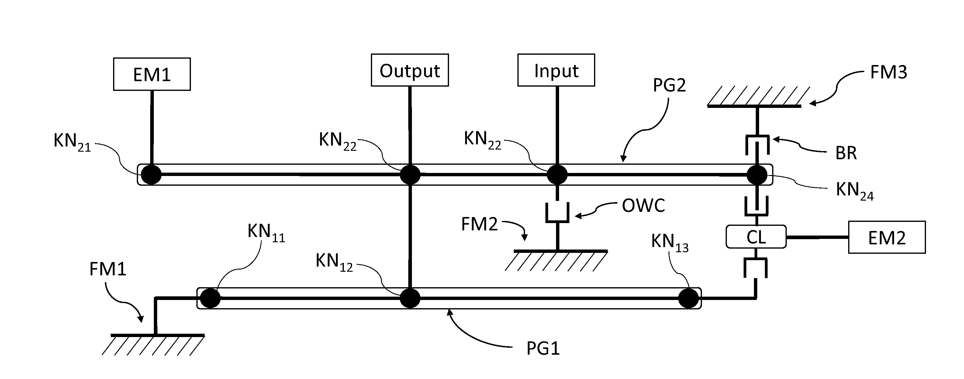
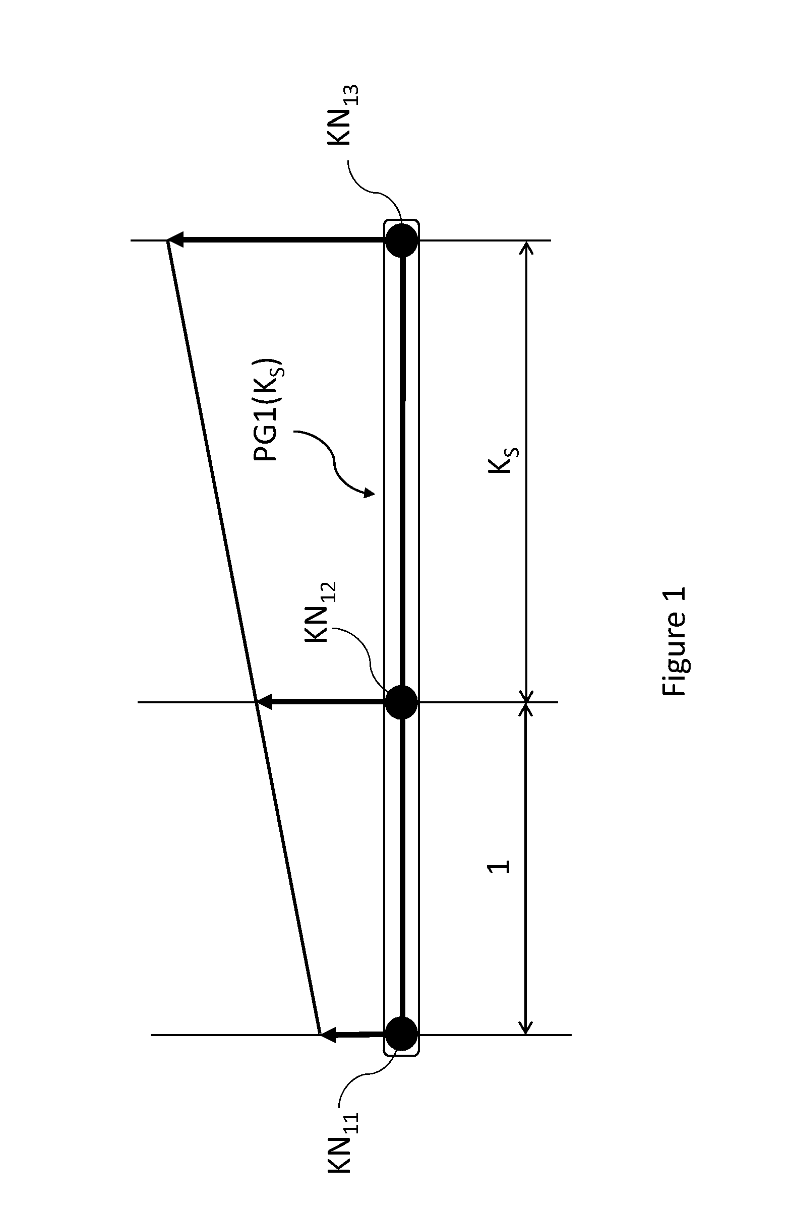
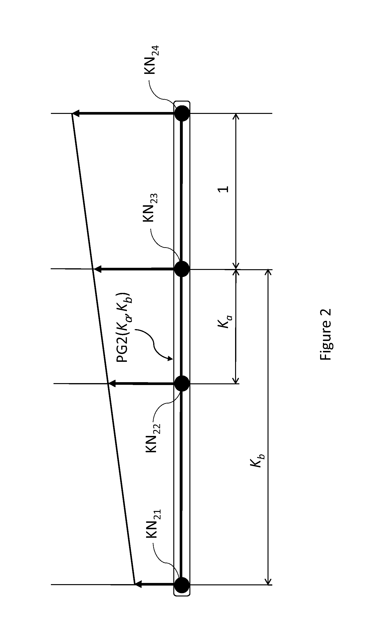
[0046]FIG. 3 and FIG. 4 show a preferred embodiment, current invention. The embodiment is illustrated in the lever diagram format. The multi-mode electro-mechanical variable speed transmission is comprised of a gear system including a first planetary gear set (PG1) represented by a first lever and a second planetary gear set (PG2) represented by a second lever, an input shaft (Input), an output system (Output), at least one clutch (CL), a first stationary member (FM1), and first and second electric machines (EM1, EM2) along with their associated drives and controllers (not shown). The first planetary gear set is a three-branch planetary gear, having a first co-axial rotatable component, a second co-axial rotatable component and a third co-axial rotatable component each represented by a first knot (KN11), a second knot (KN12) and a third knot (KN13) of the first lever, respectively. The second planetary gear set is a four-branch planetary gear set, having first, second, third and fou...

embodiment 2

[0091]FIG. 12 shows another embodiment (embodiment 2) in a lever diagram format. Referring to FIG. 12, the multi-mode electro-mechanical variable speed transmission is comprised of a gear system including a first planetary gear set (PG1) represented by a first lever and a second planetary gear set (PG2) represented by a second lever, an input shaft (Input), an output system (Output), at least one clutch (CL), a first stationary member (FM1), and first and second electric machines (EM1, EM2) along with their associated drives and controllers (not shown). The first planetary gear set is a three-branch planetary gear, having a first co-axial rotatable component, a second co-axial rotatable component and a third co-axial rotatable component each represented by a first knot (KN11), a second knot (KN12) and a third knot (KN13) of the first lever, respectively. The first lever is fully defined by its characteristic parameter KS1. The second planetary gear set is also a three-branch planeta...


PUM


Abstract

The current invention discloses a multi-mode electro-mechanical variable speed transmission. The transmission includes an input shaft, an output system, at least one planetary gear set having at least three branches each represents a co-axial rotating member, two electric machines along with the associated controllers for the electric machines, and at least a clutch. The first branch couples to the first electric machine with a constant speed ratio; the second branch couples to the output system with a constant speed ratio; and the third branch couples to the input shaft with a constant speed ratio; the second electric machine selectively couples to two different the branches of the planetary gear set with two different constant speed ratios, respectively. Said multi-mode electro-mechanical variable speed transmission is capable of providing multiple operation modes including two electric drive modes and two power split operation modes. Different operation modes cover different speed ratio regimes and are suitable for different power requirements. At the mode switching point, the corresponding clutch or clutches is automatically synchronized. This avoids shock loads during operation mode switching. The transmission is capable of providing operations with at least a fixed output to input speed ratio.

Description

CROSS-REFERENCE TO RELATED APPLICATIONS[0001]This application is a Continuation-in-Part of U.S. application Ser. No. 14 / 249,845 filed on Apr. 10, 2014, which is a Continuation of U.S. application Ser. No. 12 / 744,584 filed May 25, 2010 (now U.S. Pat. No. 8,734,281 issued May 27, 2014), which is a 371 Application of PCT / CN2008 / 001945 filed Nov. 28, 2008, which claims priority of Chinese Patent Application 200710195199.8 filed Dec. 4, 2007, all of which are incorporated herein by reference.BACKGROUND OF THE INVENTION[0002]The invention is related to a multi-mode electro-mechanical variable speed transmission in a powertrain, and to a method of operating the transmission and the powertrain. It is applicable to a wide variety of vehicles and power equipment.[0003]To reduce fuel consumption and emission, hybrid vehicles combine an electric power plant with a conventional internal combustion engine. The internal combustion engine operates in a certain range of speed and power. Inside this ...

Claims


Application Information

Patent Timeline
Patent Type & Authority Applications(United States)
IPC IPC(8): F16H3/72B60K6/445B60K6/543B60L50/15B60L50/16
CPCF16H3/728B60K6/543B60K6/445F16H2200/2007Y10S903/911F16H2200/2064F16H2200/2082F16H2200/2097F16H2200/2038B60K1/02B60K6/365B60K6/547F16H2037/0873F16H2037/101F16H2037/103F16H2037/104F16H2200/0034F16H2200/2005F16H2200/2035B60L15/2054B60L2240/12B60L2240/421B60L2240/423B60L2240/441B60L2240/443B60L2240/486F16H2200/2094F16H2200/2023B60L50/61B60L50/16B60L58/21Y02T10/62Y02T10/64Y02T10/70Y02T10/7072Y02T10/72B60W10/02B60W10/08B60W10/11
Inventor AI, XIAOLINXUE, RUIXUE, ZHONGHEAI, XIAOZHI
Owner AI XIAOLIN
Why Eureka
Try Eureka