Power transmission system for use in vehicle

a technology for power transmission systems and vehicles, applied in hybrid vehicles, gearing, instruments, etc., can solve problems such as the inability to charge vehicle-mounted batteries properly, and achieve the effect of effective use of regenerative energy

Inactive Publication Date: 2011-05-05
DENSO CORP
View PDF23 Cites 25 Cited by
  • Summary
  • Abstract
  • Description
  • Claims
  • Application Information

AI Technical Summary

Benefits of technology

[0013]According to the present invention, there is provided a power transmission apparatus for use in a vehicle of the type including a power split device to perform power distribution among a flywheel to store rotational energy as mechanical energy, an internal combustion engine and an electric rotating machine, which is capable of properly charging a vehicle battery using rotational energy stored in the flywheel to thereby make an effective use of regenerative energy.

Problems solved by technology

However, the above conventional system has a problem in that it may occur that a vehicle-mounted battery cannot be charged properly by electric energy which the electric rotating machine generates by converting the rotational energy stored in the flywheel into electric energy while the vehicle runs, because the conversion by the electric rotating machine is affected by the rotational speed of the drive wheels.

Method used


Image

  • Power transmission system for use in vehicle
  • Power transmission system for use in vehicle
  • Power transmission system for use in vehicle

Examples


first embodiment

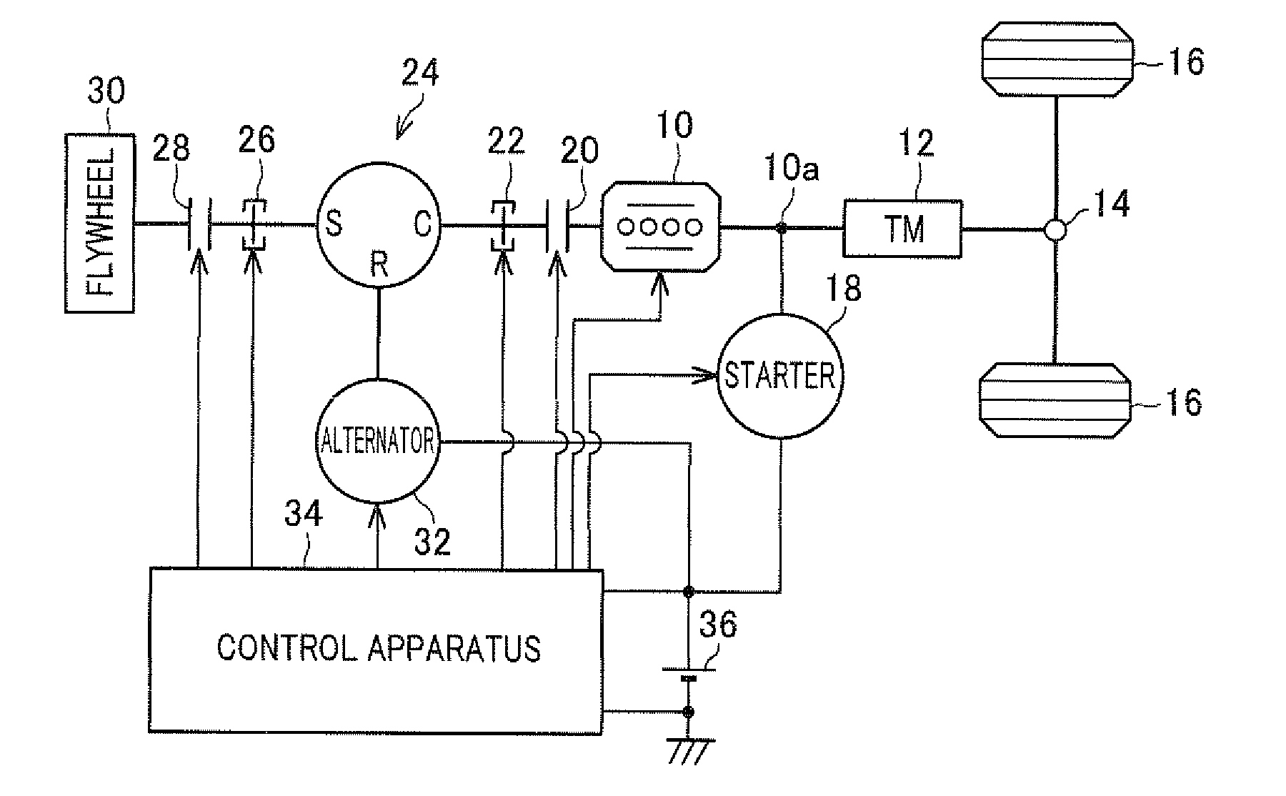
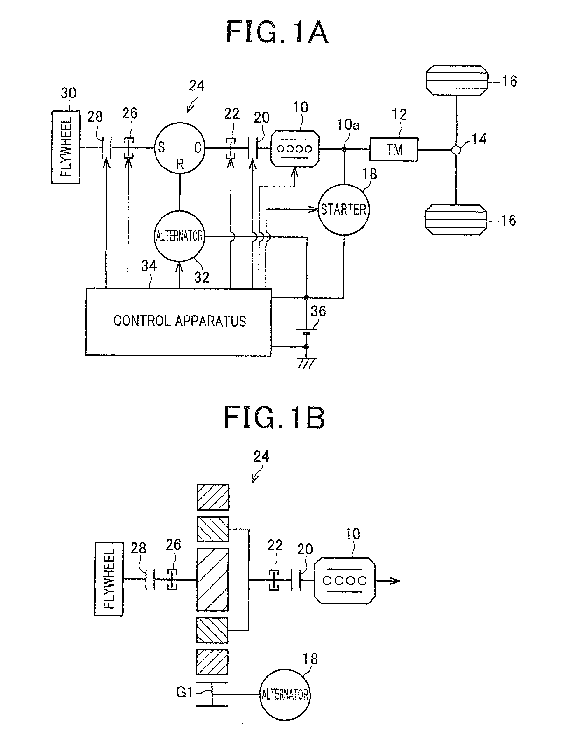
[0031]FIG. 1A is a diagram showing the structure of a power transmission system for use in a vehicle according to a first embodiment of the invention.

[0032]The first embodiment describes an application of the present invention to a vehicle having an internal combustion engine 10 as a single main engine thereof. A crankshaft 10a of the engine 10 is mechanically coupled to drive wheels 16 through a transmission 12 and a differential 14. The crankshaft 10a is provided with a starter 18 as a means to provide initial rotation to the crankshaft 10a.

[0033]The crankshaft 10a is mechanically coupled to a power split device 24 through a clutch 20 and a locking device 24 at its end not coupled to the transmission 12. The power split device 24 includes a plurality of rotating bodies which rotate in conjunction with one another, and distribute power among the engine 10, the flywheel 30 and an alternator 32. In more detail, the power split device 24 is constituted of a single planetary gear devi...

second embodiment

[0064]Next, a second embodiment of the invention is described with particular emphasis on the difference with the first embodiment.

[0065]FIG. 3 is a diagram showing the structure of a power transmission system for use in a vehicle according to a second embodiment of the invention. In FIG. 3, the reference numerals identical to those in FIG. 1 represent the same elements.

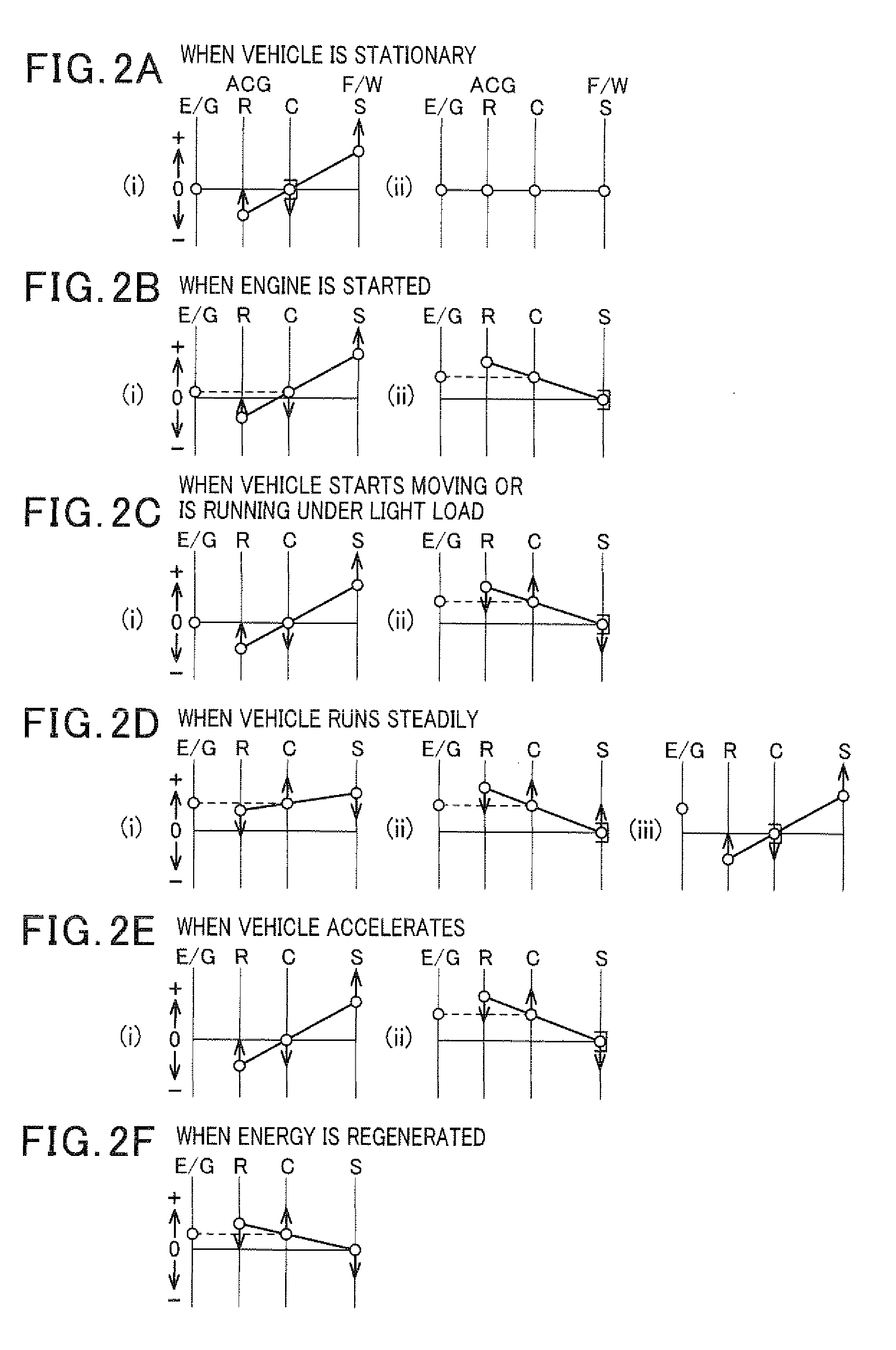
[0066]As shown in FIG. 3, in this embodiment, the starter 18 is mechanically coupled to the ring gear R. When the engine 10 is started without using the rotational energy of the flywheel 30, this makes it possible to drive the starter 18 to provide an initial rotation to the engine 10 in a state where the sun gear S is locked by the locking device 26. The rotational speeds of the ring gear R and the carrier C are the same as those shown in the section (ii) of FIG. 2B.

[0067]The second embodiment provides the following advantage in addition to the advantages (1) to (6) provided by the first embodiment.

[0068](7) The sta...

third embodiment

[0069]Next, a third embodiment of the invention is described with particular emphasis on the difference with the first embodiment.

[0070]FIG. 4 is a diagram showing the structure of a power transmission system for use in a vehicle according to a third embodiment of the invention. In FIG. 4, the reference numerals identical to those in FIG. 1 represent the same elements.

[0071]As shown in FIG. 4, in this embodiment, between the power split device 24 and the flywheel 30, there is provided a step-up device 40 which increases the rotational speed of the power split device 24. The step-up device 40 is constituted of a planetary gear device whose carrier C is mechanically coupled to the power split device 24, whose sun gear S is mechanically coupled to the flywheel 30, and whose

ring gear R is locked.

[0072]The third embodiment provides the following advantage in addition to the advantages (1) to (6) provided by the first embodiment.

[0073](8) Between the ring gear R coupled to the flywheel 30...


PUM


Abstract

The power transmission system for use in a vehicle includes a power split device to perform power distribution among a flywheel for storing rotational energy as mechanical energy, an internal combustion engine and an electric rotating machine. The power transmission system is provided with an interrupting device configured to interrupt power transmission between a group of the flywheel and the electric rotating machine and a group of the internal combustion engine and drive wheels of the vehicle when rotational energy stored in the flywheel is transmitted to the electric rotating machine through the power split device under condition that power is transmitted between the internal combustion engine and the drive wheels.

Description

[0001]This application claims priority to Japanese Patent Application No. 2009-254231 filed on Nov. 5, 2009, the entire contents of which are hereby incorporated by reference.BACKGROUND OF THE INVENTION[0002]1. Field of the Invention[0003]The present invention relates to a power transmission system for use in a vehicle including a power split device which performs power distribution among a flywheel for storing rotational energy as mechanical energy, an internal combustion engine and an electric rotating machine.[0004]2. Description of Related Art[0005]As such a power transmission system, there is the one in which a planetary gear device performs power distribution of the power between a transmission coupled to drive wheels and an internal combustion engine, the power of a flywheel, and the power of an electric rotating machine. For example, refer to International Patent Application Publication No. WO 2009 / 010819. According to this system, it is possible to store torque of the drive...

Claims


Application Information

Patent Timeline
Patent Type & Authority Applications(United States)
IPC IPC(8): B60K25/10B60W10/04B60W10/30B60W30/18B60K6/30B60K6/365B60K6/445B60K6/54B60L50/30F02D29/02F02D29/06
CPCB60K6/387Y02T10/6239Y10T477/26B60K6/40Y02T10/6204B60W10/08B60K6/105B60W20/40B60K6/30B60W10/24Y02T10/6286B60W10/06Y02T10/6282B60W10/02B60K6/445Y10S903/902B60W20/00Y02T10/62Y02T10/70B60W20/13
Inventor TANAKA, EITAROUNARITA, TAKAHIRONAGATA, TETSUYA
Owner DENSO CORP
Why Eureka
Try Eureka