Eureka AIR delivers breakthrough ideas for toughest innovation challenges, trusted by R&D personnel around the world.

Motion compatible sensor for non-invasive optical blood analysis

a sensor and optical blood analysis technology, applied in the field of optical sensors for non-invasive determination of physiological characteristics, can solve the problems of reducing the chance of the affecting the accuracy of measurement, so as to reduce the probability of oximeter locking onto a periodic motion signal and reduce the probability of signal impedement measurement, the effect of low mass

Inactive Publication Date: 2005-03-31
NELL COR PURITAN BENNETT INC (US)
View PDF26 Cites 176 Cited by
  • Summary
  • Abstract
  • Description
  • Claims
  • Application Information

AI Technical Summary

Benefits of technology

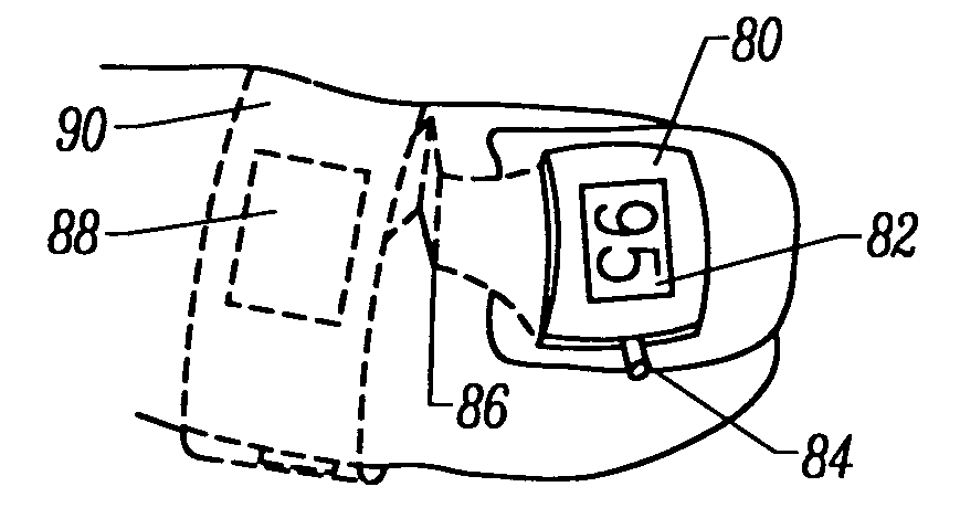
[0020] The present invention also provides an optical sensor which fits entirely on a nail. No adhesive or other securing mechanism around the rest of the finger is necessary, resulting in the entire sensor moving with the nail. The use of the nail site reduces the likelihood of out-of-phase motion signals for red and infrared wavelengths, and takes advantage of the predominantly arterial blood saturation characteristic of the blood present beneath the nail. In addition, the nail is an advantageous surface for adhering the sensor to, and at this location the method of attachment allows a low profile, low mass sensor to be used which further limits differential phase errors due to motion.

Problems solved by technology

Motion can cause a false signal peak and valley, resulting in a measurement having an inaccurate value and one which is recorded at the wrong time.
This reduces the chances of the oximeter locking onto a periodic motion signal.
The motion signal impedes the measurement because it obscures the cardiac signal.
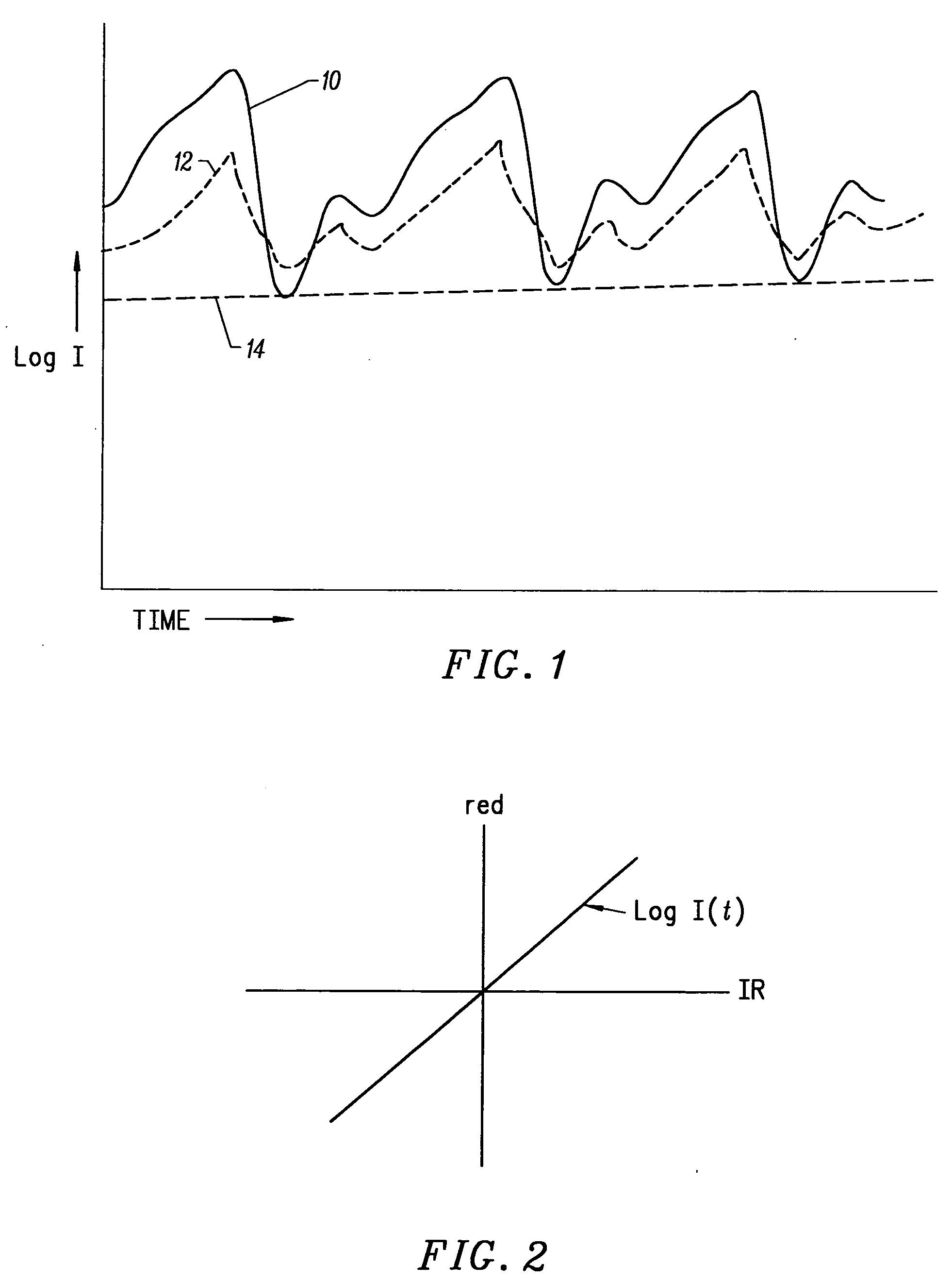
The red and infrared intensity signals are often not in phase, and can limit the use of the motion signal for calculating oxygen saturation.
Motion will cause disproportionate variances in the path lengths of the two wavelengths of light, resulting in out-of-phase signals of the detector.

Method used


Image

  • Motion compatible sensor for non-invasive optical blood analysis
  • Motion compatible sensor for non-invasive optical blood analysis
  • Motion compatible sensor for non-invasive optical blood analysis

Examples


Embodiment Construction

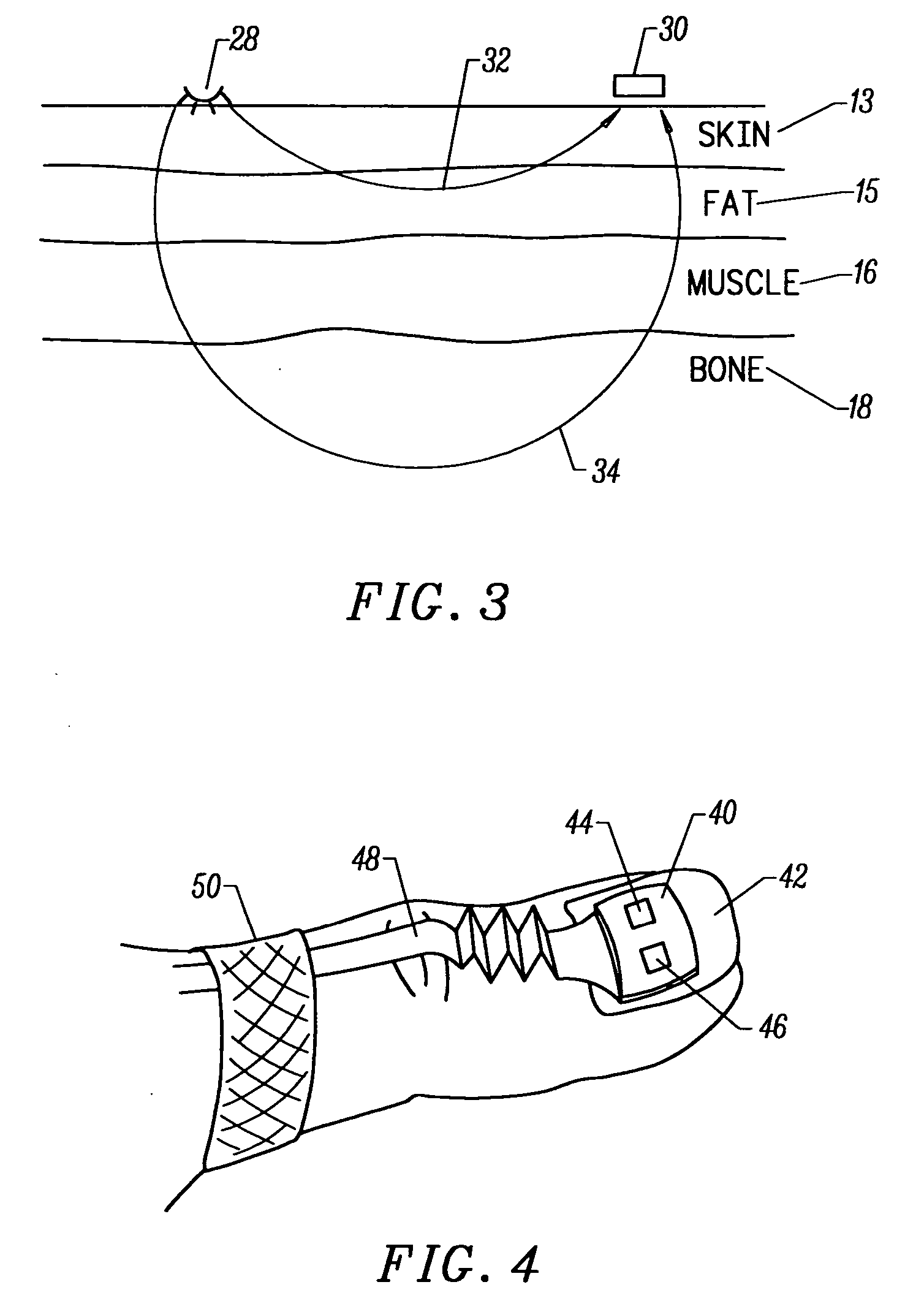
[0043]FIG. 4 illustrates a sensor 40 according to the present invention preferably mounted on a nail 42 (a thumbnail or any other digit may be used). The sensor is held on with adhesive, and has an emitter 44 and a detector 46. A flexible circuit 48 provides the electrical connections to the emitter and detector, and may be accordion-shaped between the sensor and a securing band 50 to provide additional strain relief. This isolates the sensor from tugging or pulling on the electrical connection cord from either the sensor side or the other direction. Band 50 may be, for instance, an elastic band, cloth wrap secured with Velcro™, or another device. Flexible circuit 48 could be electrical wires or fiber optic cables. The different wavelength light could be premixed using the fiber optic cable.

[0044] The placement on the top of the nail allows the cable to extend along the top of the finger or other digit, without the sensor or the cable being on the palmar side of the digit where it ...


PUM


Abstract

A non-invasive optical sensor which uses the motion signal to calculate the physiological characteristic being measured. For pulse oximetry, a least squares or a ratio-of-ratios technique can be applied to the motion signal itself. This is made possible by selecting a site on the patient where variations in motion produce signals of two wavelengths which are sufficiently correlated. In particular, it has been determined that a sensor placed on a nail, in particular a thumbnail, exhibits the characteristics of having the red and infrared signals correlated when used for pulse oximetry, and the resulting signals correlate to arterial oxygen saturation.

Description

CROSS-REFERENCES TO RELATED APPLICATIONS [0001] This application is a continuation of U.S. application Ser. No. 10 / 080,433, filed Feb. 21, 2002, now U.S. Pat. No. ______, which is a division of U.S. application Ser. No. 09 / 348,437, filed Jul. 7, 1999, now U.S. Pat. No. 6,374,129, which is a division of U.S. application Ser. No. 08 / 722,443, filed Oct. 10, 1996, now U.S. Pat. No. 6,018,673, which disclosures are incorporated by reference for all purposes.STATEMENT AS TO RIGHTS TO INVENTIONS MADE UNDER FEDERALLY SPONSORED RESEARCH OR DEVELOPMENT [0002] NOT APPLICABLE REFERENCE TO A “SEQUENCE LISTING,” A TABLE, OR A COMPUTER PROGRAM LISTING APPENDIX SUBMITTED ON A COMPACT DISK [0003] NOT APPLICABLE BACKGROUND OF THE INVENTION [0004] The present invention relates to optical sensors for non-invasive determination of physiological characteristics, and in particular to sensors for making such determinations in the presence of motion. [0005] Many types of optical sensors are used to measure ...

Claims


Application Information

Patent Timeline
Patent Type & Authority Applications(United States)
IPC IPC(8): A61B5/00A61B5/145A61B5/1455A61B5/1464A61B5/1495
CPCA61B5/14552A61B5/6826A61B5/6833A61B5/7207A61B5/6838
Inventor CHIN, RODNEYMANNHEIMER, PAULFLEWELLING, ROSS
Owner NELL COR PURITAN BENNETT INC (US)
Why Eureka
Eureka Blog
Learn More