Two-compartment reduced volume infusion pump

Active Publication Date: 2005-03-31
CODMAN & SHURTLEFF INC
20 Cites 135 Cited by

AI-Extracted Technical Summary

Problems solved by technology

Thus, neither Speckman nor Powers allows for the contents of the reservoirs to be mixed prior to di...

Method used

[0028] In addition to reducing the size of the implantable infusion apparatus, the invention can reduce or shorten the number or length of a patient's doctor visits. Typically, only a doctor can refill medication reservoir 102. But, because medication 104 is highly concentrated and then diluted with carrier 108, the doctor will not be required to fill medication reservoir 102 as often. Carrier reservoir 106 is only filed with a non-medication substance. Since carrier 108 is not a medication, either the patient at home, or a nurse can refill carrier reservoir 106. In one embodiment, carrier compound septum 120 is larger and/or differently shaped than the medication compound septum 118 to ...

Benefits of technology

[0008] The carrier reservoir is larger and thus holds a larger volume than the medication reservoir. To reduce the size of the implantable infusion pump apparatus, the medication is highly concentrated to many times the dosage required. The concentrated medi...

Abstract

An implantable infusion apparatus has a medication reservoir for storing a medication and a carrier reservoir for storing a carrier. The entire apparatus, including both reservoirs, is typically located in a housing made of stainless steel, titanium, or any other strong corrosion resistant biocompatible material. The medication and carrier reservoirs are accessed through a medication access port and a carrier access port, respectively. The access ports are covered with a medication compound septum and a carrier compound septum, respectively. The carrier reservoir is larger, and thus holds a larger volume, than the medication reservoir. To reduce the size of the implantable infusion apparatus, the medication is highly concentrated to many times the dosage required. The concentrated medication is then diluted with the carrier, to the proper dose, before it is discharged to the patient.

Application Domain

Flow mixersTransportation and packaging +4

Technology Topic

Corrosion resistantTitanium +6

Image

  • Two-compartment reduced volume infusion pump
  • Two-compartment reduced volume infusion pump
  • Two-compartment reduced volume infusion pump

Examples

  • Experimental program(1)

Example

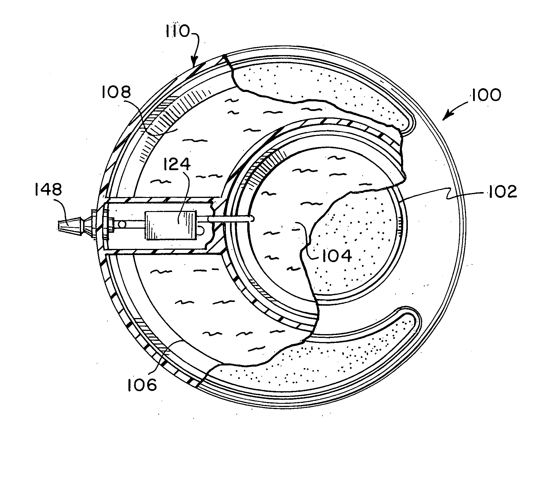
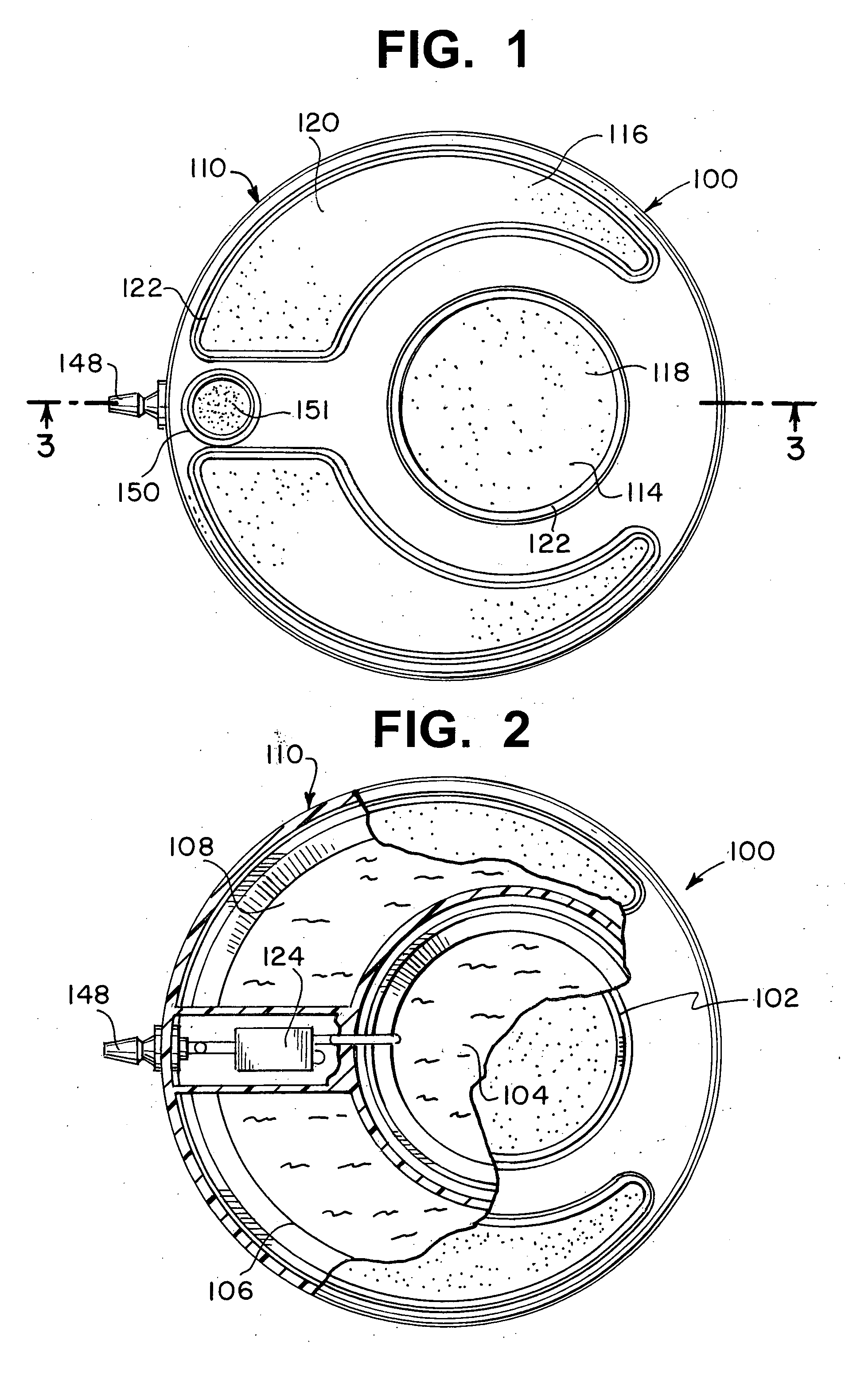
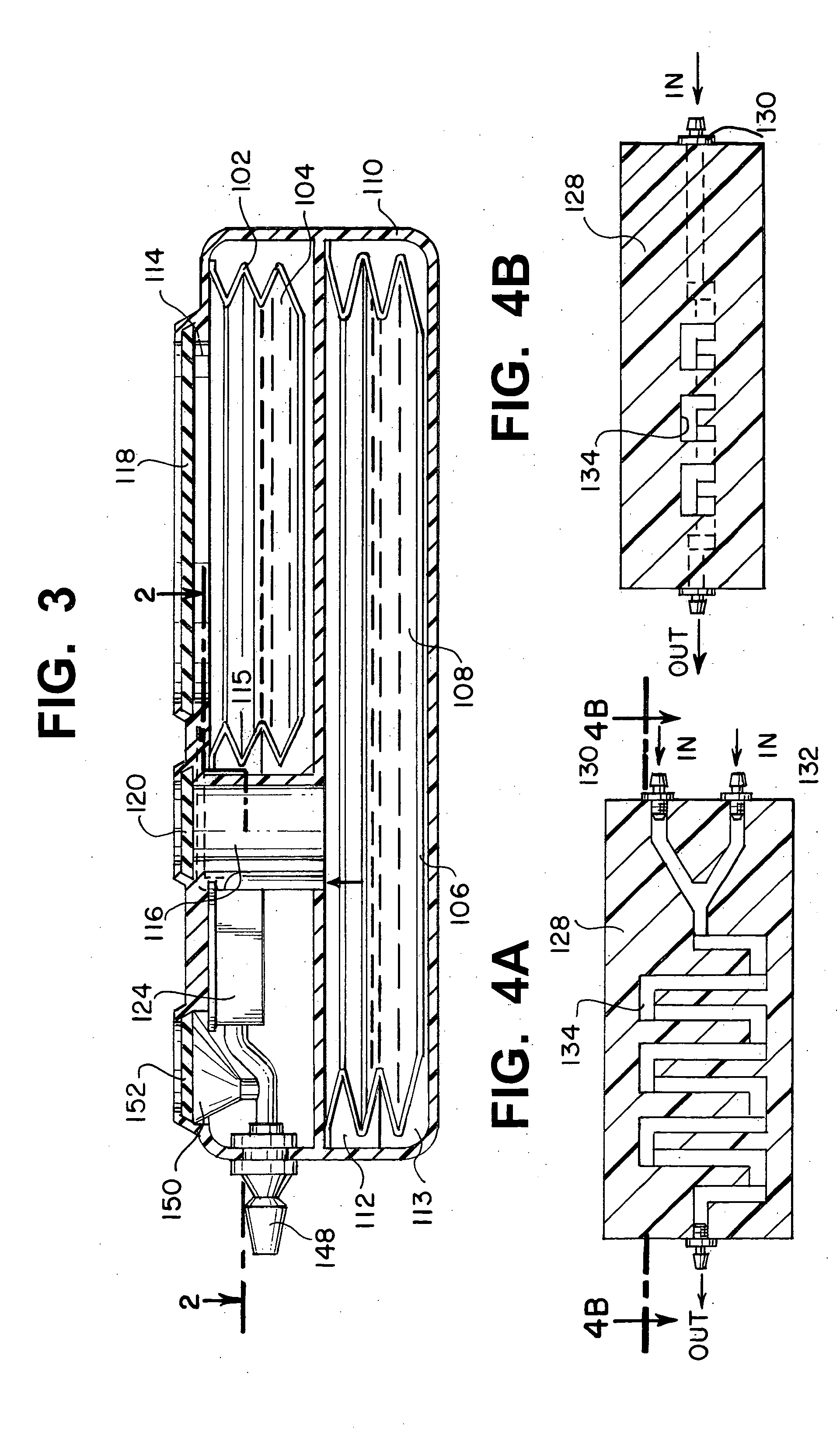
[0026] Referring now to FIGS. 1 and 2, an implantable infusion apparatus 100 in accordance with the present invention is illustrated. FIG. 2 illustrates a medication reservoir 102 for storing a medication 104 and a carrier reservoir 106 for storing a carrier 108. The entire apparatus, including both reservoirs, is typically located in a housing 110. Housing 110 can be made of stainless steel, titanium, or any other strong corrosion-resistant, biocompatible material. The reservoirs are typically in the form of a bellows 112 (FIG. 3) that expands and contracts with the discharge and replenishment of the liquid inside. FIG. 1 illustrates that medication reservoir 102 and carrier reservoir 106 are accessed through a medication access port 114 and a carrier access port 116, respectively. Access ports 114, 116 are covered with a medication compound septum 118 and a carrier compound septum 120, respectively. Both compound septa 118, 120 are formed from elastomeric, needle-penetrable, self-sealing material that enables needles to access the reservoirs. Additionally, access to reservoirs 102, 106 can be gained through any number of valve, needle, and needle stop configurations as known in the art. Further, tactile ridges 122 can be formed on the housing around access ports 114, 116 to allow a doctor, nurse, or patient to locate access ports 114, 116 by palpating the skin. Once tactile ridges 122 are located, it is immediately known where medication compound septum 118 and carrier compound septum 120 are located below the skin. The placement and shape of the ridges are well known by those of skill in the art.
[0027]FIGS. 2 and 3 illustrate that carrier reservoir 106 is larger than medication reservoir 102. To reduce the size of implantable infusion apparatus 100, medication 104 is highly concentrated to many times the dosage required. Concentrated medication 104 is then diluted with carrier 108 before it is discharged to the patient. Carrier 108 is typically saline or other sterile liquid carrier. Carrier reservoir 106 can be about 4 to about 5 times the size as medication reservoir 102. For example, carrier reservoir 106 can hold 20 ml and the medication can be about 4 ml or about 5 ml and the above arrangement can replace one 40 ml reservoir.
[0028] In addition to reducing the size of the implantable infusion apparatus, the invention can reduce or shorten the number or length of a patient's doctor visits. Typically, only a doctor can refill medication reservoir 102. But, because medication 104 is highly concentrated and then diluted with carrier 108, the doctor will not be required to fill medication reservoir 102 as often. Carrier reservoir 106 is only filed with a non-medication substance. Since carrier 108 is not a medication, either the patient at home, or a nurse can refill carrier reservoir 106. In one embodiment, carrier compound septum 120 is larger and/or differently shaped than the medication compound septum 118 to assist the patient in locating carrier reservoir 106. An alternate embodiment can provide a single access port for both reservoirs wherein only a particular type of needle (e.g. by length or location of the discharge orifice) can access each of the reservoirs. The above safeguards can allow a patient to safely refill carrier reservoir 106. The location of access ports 114, 116 with respect to pump housing 110 can also assist the patient/nurse/doctor in distinguishing between carrier access port 116 and medication access port 114. For example, medication access port 114 can be disposed in the center of housing 110 and carrier access port 116 can be disposed along housing's 110 perimeter.
[0029] A mixing chamber 124 is included to thoroughly mix and dilute medication 104 with carrier 108. Mixing chamber 124 must allow for full dilution and mixing of carrier 108 with medication 104 or the patient will receive an improper dose. One embodiment, as illustrated in FIGS. 4A and 4B, uses a microfluidic chip 128 to mix the two substances. Microfluidic chip 128 can have a medication input 130 and a carrier input 132 and capillary pathway 134 is configured in a serpentine pattern. The capillary pathway 134 can include convolutions in vertical and horizontal planes to the direction of flow. The convolutions act to allow medication 104 sufficient contact time with carrier 108 to allow for thorough mixing. Examples of microfluidic mixing chips include U.S. Patent Publication No. 2001/0048900, to Bardell et al.; U.S. Patent Publication No. 2003/0040105 to Sklar et al.; and U.S. Patent Publication No. 2003/0133358 to Karp. Other microfluidic mixing chips and mixing chambers to allow for thorough mixing are known to those of skill in the art.
[0030] One key to the mixing process is controlling the flow of both medication 104 and carrier 108 from reservoirs 102, 106 to mixing chamber 124. The flow rate can be controlled in numerous ways described below.
[0031] Referring now to FIGS. 5 through 9, a medication flow path 136 fluidly connects medication reservoir 102 to mixing chamber 124 and a carrier flow path 138 fluidly connects carrier reservoir 106 to mixing chamber 124. The flow paths can simply act as conduits between the reservoirs and the mixing chamber. FIG. 5 illustrates one embodiment that alters the physical properties of medication flow path 136 so it is less restrictive than carrier flow path 138. Conversely, FIG. 6 illustrates that medication flow path 136 is more restrictive than carrier flow path 138. The restrictive nature of a flow path is a factor in determining the flow rate of the fluid inside the path. For example, as illustrated in FIG. 5, medication flow path 136 can be designed with a larger diameter A than a smaller diameter B of carrier flow path 138. FIG. 6 illustrates that larger diameter A of carrier flow path 138 can be larger than smaller diameter B of medication flow path 136. The restrictions in the flow path can also be built into microfluidic chip 128, after inputs 130, 132, and before mixing chamber 124. FIG. 4C illustrates a medication reduced diameter section 131, internal to microfluidic chip 128 that can act as the restriction to flow. Alternately, a carrier reduced diameter section 133 can also be disposed internal to microfluidic chip 128 to restrict the flow of carrier 108. FIG. 4C illustrates both medication and carrier reduced diameter sections 131, 133, however, the reduced diameter sections can be used together or only one section can be restricted.
[0032] Additional embodiments, as illustrated in FIGS. 7 through 9, dispose either a medication flow restrictor 140 in medication flow path 136 to restrict the flow of medication 104 between medication reservoir 102 and mixing chamber 124; a carrier flow restrictor 142 in carrier flow path 138 to restrict the flow of carrier 108 between carrier reservoir 106 and mixing chamber 124; or both flow restrictors 140, 142 can be included in the same apparatus, as illustrated in FIG. 7. Flow restrictors 140, 142 can be physical changes to flow paths 136, 138 or microfluidic chips (not illustrated), depending on the configuration and flow rate required. As above, either flow restrictor 140, 142 can be more or less restrictive than the other.
[0033] Referring to FIG. 8, a medication pump system 144 is used to discharge medication 104 to mixing chamber 124 and a carrier pump system 146 is used to discharge carrier 108 to mixing chamber 124. Medication pump system 144 has a medication discharge rate Qm and carrier pump system 146 has a carrier discharge rate Qc. As above, to properly control the mixing of medication 104 with carrier 108, the proper flows must be determined so the proper amount of medication 104 is diluted with the proper amount of carrier 108, depending on the dose to be administered to the patient. Discharge rates Qm, Qc can be configured in many ways, for example, medication discharge rate Qm can equal carrier discharge rate Qc and the flow can be restricted down stream of the pump by either flow paths 136, 138 or flow restrictors 140, 142. Alternately, medication discharge rate Qm can be greater than or less than carrier discharge rate Qc or any combination of flow paths 136, 138, flow restrictors 140, 142 and discharge rates Qm, Qc can be used to control the flow of both carrier 108 and medication 104.
[0034] Pump systems 144, 146 can be any pumping system known to those of skill in the art, including a power cell 113, 115 associated with the medication and the carrier reservoirs, respectively. Power cells 113, 115 can be a two-phase fluid power cell, where the fluid in the power cell vaporizes at physiological temperatures. The gas formed from the vaporization of the fluid forces the reservoir to contract and expel the medication or carrier contained therein. When the reservoir is refilled, the reservoir is forced to expand against the vaporized liquid and the vaporized liquid condenses. Another power cell 113, 115 embodiment pressurizes the area surrounding medication and carrier reservoirs 102, 106 with a propellant, such as butane or Freon. The positive pressure of the propellant forces fluid out of reservoirs 102, 106 through one or both flow restrictors 140, 142 or microfluidic restrictors 131, 133. The combination of constant pressure and constant fluidic resistance due to the restrictors results in a constant discharge rates Qm, Qc. Additionally, a traditional battery operated system can be used to discharge medication 104 and carrier 108.
[0035] An outlet port 148 (FIGS. 1 and 10) is fluidly connected to mixing chamber 124 for discharging a diluted medication/carrier mixture to the patient. Outlet port 148 can be positioned and configured numerous ways to connect to a catheter (not illustrated) leading anywhere in the body.
[0036] The embodiment of implantable infusion apparatus 100 shown in FIG. 10 further includes a bolus port 150 disposed between mixing chamber 124 and outlet port 148. Bolus port 150 allows a doctor to introduce a bolus dose into apparatus 100, after medication 104 and carrier 108 have been mixed, but prior to the diluted mixture being discharged from apparatus 100. Bolus port 150 can be covered by a bolus compound septum 151 (FIG. 1) made of similar material to the septa described above. Additionally, bolus port 150 can be accessed from a common access port shared with the reservoirs and configured for another type of needle.
[0037] Referring now to FIG. 9, another embodiment of an implantable infusion apparatus 100 is illustrated. FIG. 9 illustrates an electronically controlled medication flow selector 152 disposed in medication flow path 136 for controlling a selected medication discharge rate Qms of medication 106 to mixing chamber 124. Using medication flow selector 152, a doctor can alter the dosage of medication a patient receives without completely draining medication 104 from medication reservoir 102 and replacing it with a higher or lower concentration of medication 104. By altering the flow, a doctor can control how much medication 104 is mixed with carrier 108, and thus control the dosage. Another embodiment utilizes a carrier flow selector 154 disposed in carrier flow path 138 for controlling a selected carrier discharge rate Qcs of carrier 108 to mixing chamber 124. Controlling the discharge rate of the carrier also affects the dosage. Both medication flow selector 152 and carrier flow selector 154 can be made of a valve 156 or a pump 158 (FIGS. 8 and 9). An electronic device, such as a timer or a remote control, can control either valve 156 or pump 158. Flow selector 152 can be set to increase or decrease the amount of medication 104 that enters mixing chamber 124 based on a preset time. Additionally, telemetric remote controls can alter the programming of flow selectors 152, 154 through the skin of the patient. All of the other elements of the implantable infusion apparatus containing medication flow selector 152 are similar to the elements described in the above embodiments. Thus, embodiments of implantable infusion apparatus 100 include constant flow, wherein the flow rates of both the medication and the carrier are fixed prior to implanting the infusion apparatus into the patent; programmable flow, wherein the infusion apparatus contains electronics that are programmed to alter the flow of the medication and/or the carrier to vary the dosage to the patent at different times; and adjustable flow models that provide a constant flow of the medication and carrier but the medication and/or carrier flow rate can be adjusted by a doctor to alter the flow rate of the constant flow.
[0038]FIGS. 10 and 11 are schematic diagrams illustrating typical embodiments for the present invention. FIG. 10 schematically illustrates medication access port 114 in-line with medication reservoir 102. Medication flow path 136 fluidly connects medication reservoir 102 to mixing chamber 124 via medication flow restrictor 140. Carrier access port 116 is fluidly connected to carrier reservoir 106 and carrier flow path 138 fluidly connects carrier reservoir 106 to mixing chamber 124 via carrier flow restrictor 142. Further, bolus port 150 is disposed in the flow path between mixing chamber 124 and outlet 148 to permit the injection of a bolus dose. FIG. 11 illustrates another embodiment wherein medication flow selector 154 is located in the flow path between medication flow restrictor 140 and mixing chamber 124 to allow additional control of medication discharge rate Qm.
[0039]FIG. 12 illustrates a method of infusing medication including storing a medication in a medication reservoir (step 200) and storing a carrier in a carrier reservoir (step 202). The carrier reservoir is sized larger than the medication reservoir. Approximately simultaneously, the medication is discharged to a mixing chamber (step 204) and the carrier is discharged to the mixing chamber (step 206). Once in the mixing chamber, the medication is mixed with the carrier to dilute it (step 208); and then the diluted medication/carrier mixture is discharged (step 210). As an additional step, a bolus dosage may be introduced into the diluted medication/carrier mixture prior to discharging the diluted medication/carrier mixture (step 212).
[0040] Another embodiment can restrict the discharge of the medication (step 214), restrict the discharge of the carrier (step 216) or restrict both. When both the medication and the carrier are restricted, the discharge of the medication can be restricted more than the discharge of the carrier (step 218) or the carrier can be more restricted than the discharge of the medication (step 220). Other embodiments restrict the discharge of both the medication and the carrier to a certain extent to provide a constant flow rate to counter the constant action of the pumping system.
[0041] Further, FIG. 13 illustrates that the dilution step can include contacting the medication with the carrier in the mixing chamber (step 222); flowing the contacted medication/carrier mixture through a series of mixing elements (step 224); and delaying the discharging of the diluted medication/carrier mixture until the medication is diluted to the proper dosage (step 226). The mixing elements can be baffles, hydraulic turbulence, or other mixing elements found in microfluidic devices.
[0042]FIG. 14 illustrates another embodiment that adds the step of controlling the discharge of the medication into the mixing chamber (step 228). The electronic flow selectors as described above can perform the step of controlling the discharge of the medication.
[0043] Thus, while there have been shown, described, and pointed out fundamental novel features of the invention as applied to a preferred embodiment thereof, it will be understood that various omissions, substitutions, and changes in the form and details of the devices illustrated, and in their operation, may be made by those skilled in the art without departing from the spirit and scope of the invention. For example, it is expressly intended that all combinations of those elements and/or steps which perform substantially the same function, in substantially the same way, to achieve the same results are within the scope of the invention. Substitutions of elements from one described embodiment to another are also fully intended and contemplated. It is also to be understood that the drawings are not necessarily drawn to scale, but that they are merely conceptual in nature. It is the intention, therefore, to be limited only as indicated by the scope of the claims appended hereto.

PUM

no PUM

Description & Claims & Application Information

We can also present the details of the Description, Claims and Application information to help users get a comprehensive understanding of the technical details of the patent, such as background art, summary of invention, brief description of drawings, description of embodiments, and other original content. On the other hand, users can also determine the specific scope of protection of the technology through the list of claims; as well as understand the changes in the life cycle of the technology with the presentation of the patent timeline. Login to view more.

Similar technology patents

Projection display apparatus

ActiveUS11190740B2large volumeincrease volume
Owner:SONY CORP

Material transport cart

InactiveCN104859443ASimple structurelarge volume
Owner:康昌文

Computing environment system for monitoring aircraft engines

PendingUS20220076581A1large volumereduce number
Owner:SN DETUDE & DE CONSTR DE MOTEURS DAVIATION S N E C M A

Novel separation device

InactiveCN104148285Alarge volumeImprove efficiency
Owner:杨配媛

Motor-driven continuous circulating elevator system

ActiveCN106348132Alarge volume
Owner:南宁邃丛赋语科技开发有限责任公司

Classification and recommendation of technical efficacy words

  • large volume
  • reduce in size

Non-visible particle detection based on smart phone

InactiveUS20120273688A1large volumehigh maintenance cost
Owner:NAT APPLIED RES LAB

Apparatus and method for generating pulse laser

InactiveUS20150372447A1costly maintenance costlarge volume
Owner:ELECTRONICS & TELECOMM RES INST

Methods for fabricating electrokinetic concentration devices

InactiveUS20090242406A1large volume
Owner:MASSACHUSETTS INST OF TECH

Spindle head for a universal milling machine

InactiveUS20050217095A1reduce delaylarge volume
Owner:DECKEL MAHO PFRONTEN GMBH

Pneumatic tire

ActiveUS20130068359A1generate wearlarge volume
Owner:TOYO TIRE & RUBBER CO LTD

Device and method of arthroscopic knee joint resurfacing

InactiveUS20050137708A1reduce in sizeload share
Owner:CLARK RON

Making electrical components in handle wafers of integrated circuit packages

ActiveUS9165793B1reduce in sizemaximization of size and capacity
Owner:INVENSAS CORP

Offset remote center manipulator for robotic surgery

ActiveUS20060074406A1reduce in sizeenhance range
Owner:INTUITIVE SURGICAL OPERATIONS INC

Stent

Owner:BIOTRONIK MESTRASSE UND THERAPIEGERATE GMBH & CO ING BERLIN
Why Eureka
Try Eureka