Signal modification method for efficient coding of speech signals

a signal modification and speech signal technology, applied in the field of sound signal encoding and decoding, can solve the problem of consuming a substantial proportion of the available bit budg

Active Publication Date: 2005-03-31
NOKIA TECHNOLOGLES OY
View PDF8 Cites 53 Cited by
  • Summary
  • Abstract
  • Description
  • Claims
  • Application Information

AI Technical Summary

Problems solved by technology

At low bit rates, these parameters consume a substantial proportion of the available bit budget.

Method used


Image

  • Signal modification method for efficient coding of speech signals
  • Signal modification method for efficient coding of speech signals
  • Signal modification method for efficient coding of speech signals

Examples


Embodiment Construction

Although the illustrative embodiments of the present invention will be described in relation to speech signals and the 3GPP AMR Wideband Speech Codec AMR-WB Standard (ITU-T G.722.2), it should be kept in mind that the concepts of the present invention may be applied to other types of sound signals as well as other speech and audio coders.

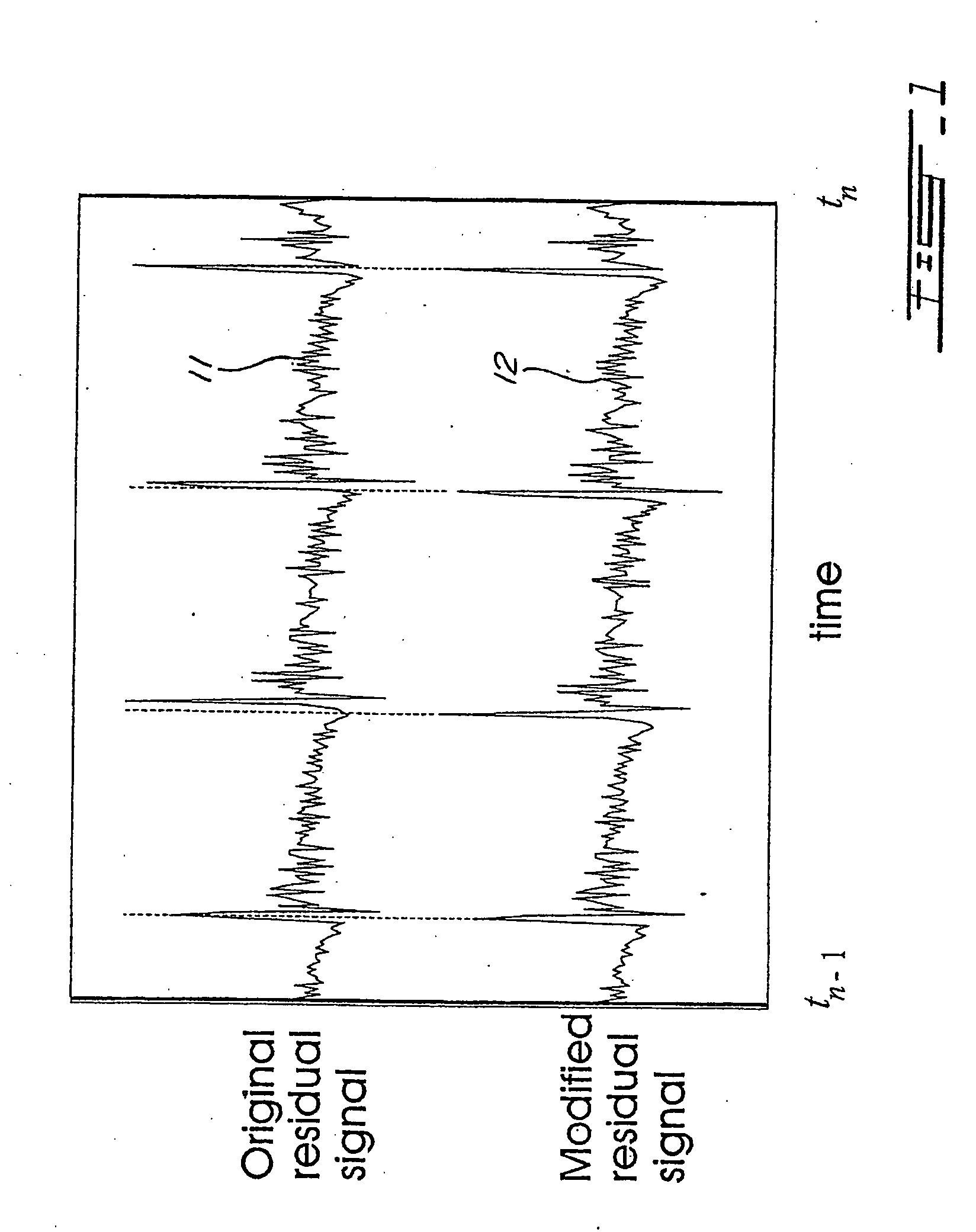
FIG. 1 illustrates an example of modified residual signal 12 within one frame. As shown in FIG. 1, the time shift in the modified residual signal 12 is constrained such that this modified residual signal is time synchronous with the original, unmodified residual signal 11 at frame boundaries occurring at time instants tn−1 and tn. Here n refers to the index of the present frame.

More specifically, the time shift is controlled implicitly with a delay contour employed for interpolating the delay parameter over the current frame. The delay parameter and contour are determined considering the time alignment constrains at the above-mentioned frame bou...


PUM


Abstract

For determining a long-term-prediction delay parameter characterizing a long term prediction in a technique using signal modification for digitally encoding a sound signal, the sound signal is divided into a series of successive frames, a feature of the sound signal is located in a previous frame, a corresponding feature of the sound signal is located in a current frame, and the long-term-prediction delay parameter is determined for the current frame while mapping, with the long term prediction, the signal feature of the previous frame with the corresponding signal feature of the current frame. In a signal modification method for implementation into a technique for digitally encoding a sound signal, the sound signal is divided into a series of successive frames, each frame of the sound signal is partitioned into a plurality of signal segments, and at least a part of the signal segments of the frame are warped while constraining the warped signal segments inside the frame. For searching pitch pulses in a sound signal, a residual signal is produced by filtering the sound signal through a linear prediction analysis filter, a weighted sound signal is produced by processing the sound signal through a weighting filter, the weighted sound signal being indicative of signal periodicity, a synthesized weighted sound signal is produced by filtering a synthesized speech signal produced during a last subframe of a previous frame of the sound signal through the weighting filter, a last pitch pulse of the sound signal of the previous frame is located from the residual signal, a pitch pulse prototype of given length is extracted around the position of the last pitch pulse of the sound signal of the previous frame using the synthesized weighted sound signal, and the pitch pulses are located in a current frame using the pitch pulse prototype.

Description

FIELD OF THE INVENTION The present invention relates generally to the encoding and decoding of sound signals in communication systems. More specifically, the present invention is, concerned with a signal modification technique applicable to, in particular but not exclusively, code-excited linear prediction (CELP) coding. BACKGROUND OF THE INVENTION Demand for efficient digital narrow- and wideband speech coding techniques with a good trade-off between the subjective quality and bit rate is increasing in various application areas such as teleconferencing, multimedia, and wireless communications. Until recently, the telephone bandwidth constrained into a range of 200-3400 Hz has mainly been used in speech coding applications. However, wideband speech applications provide increased intelligibility and naturalness in communication compared to the conventional telephone bandwidth. A bandwidth in the range 50-7000 Hz has been found sufficient for delivering a good quality giving an impr...

Claims


Application Information

Patent Timeline
Patent Type & Authority Applications(United States)
IPC IPC(8): G10L19/12
CPCG10L19/08G10L19/09G10L19/12
Inventor TAMMI, MIKKOJELINEK, MILANLAFLAMME, CLAUDERUOPPILA, VESA
Owner NOKIA TECHNOLOGLES OY
Why Eureka
Try Eureka