Manifold valve

Inactive Publication Date: 2005-04-07
ASAHI YUKIZAI KOGYO CO LTD
View PDF10 Cites 36 Cited by
  • Summary
  • Abstract
  • Description
  • Claims
  • Application Information

AI Technical Summary

Benefits of technology

[0004] Accordingly, an object of the present invention is to provide a mani

Problems solved by technology

However, in the former method shown in FIG. 18, there are caused a problem in that a slurry stagnates in the flow passage portions from the T-shaped pipes 204, 205 to the two-way valves 202, 203, respectively, and a problem in that the flow passage portions from the three-way valves 200, 201

Method used


Image

  • Manifold valve
  • Manifold valve
  • Manifold valve

Examples


first embodiment

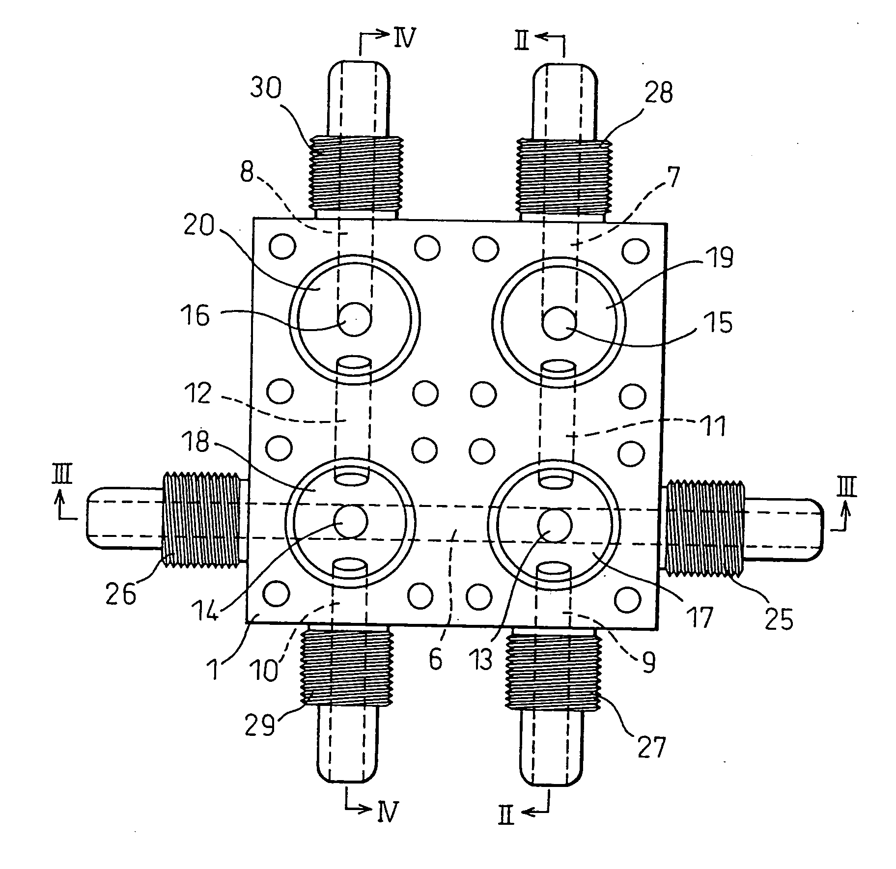
[0046] Next, the operation of the manifold valve according to the present invention shown in FIG. 1 will be described below.

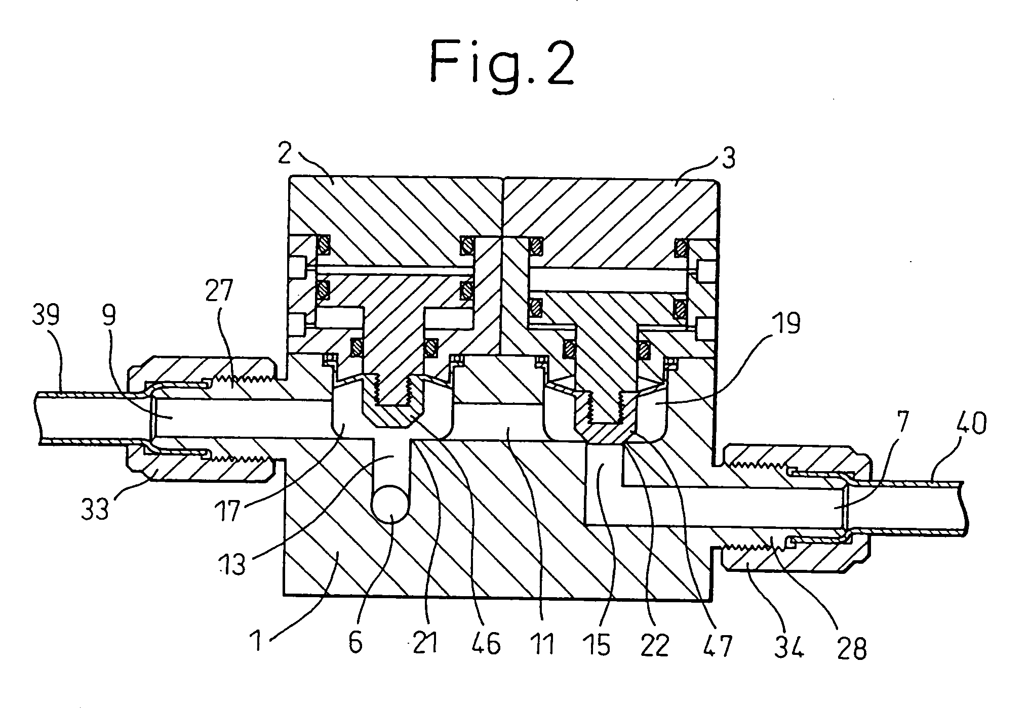
[0047]FIGS. 2 and 3 illustrate the condition in which the main flow passage-side communication port 13 is opened and the secondary flow passage-side communication port 15 is closed. In this condition, the fluid in the main flow passage 6 flows to the secondary flow passage-side valve chamber 19, the connecting flow passage 11, the main flow passage-side valve chamber 17 and the branched flow passage 9. When the working fluid (for example, a compressed air etc.) is supplied from the outside through the working fluid supply port 64 of the actuator 2 shown in FIG. 5 into the upper space 62 in this condition, the piston 52 is pushed down by the pressure of the working fluid, so that the valve body 46 connected to the lower end of the rod portion 58 is pressed against the valve seat 21 to close the main flow passage-side communication port 13. On the other hand, whe...

fourth embodiment

[0058]FIG. 17 illustrates an external appearance view of a branched chemical liquid supply line in which the manifold valve according to the present invention is applied to the above-mentioned prior art. In the drawing, reference numeral 151 designates a manifold valve according to the present invention; reference numeral 152 designates a main flow passage; reference numeral 153 designates a secondary flow passage; and reference numerals 154 and 155 designate branched flow passages, respectively. As can be seen from the drawing, comparing with the conventional lines shown in FIGS. 18 and 19, the number of valves and T-shaped pipes can be reduced, i.e., one valve according to this embodiment is sufficient to meet the requirements. Thus, the piping line can be simplified, the piping space can be smaller, and the laying of lines can be easily performed.

[0059] The manifold valve according to the present invention has a construction as described above and thus the following superior effe...


PUM


Abstract

A manifold valve according to the present invention includes a main body (1) and actuators (2, 3) each having a valve body (46, 47). The main body is formed with at least one set of a main flow passage-side valve chamber (17) and a secondary flow passage-side valve chamber (19) which are in communication with each other through a connecting flow passage (11), a branched flow passage (9) communicating with the main flow passage-side valve chamber, a-main flow passage (6) communicating with the main flow passage-side valve chamber through a main flow passage-side communication port (13) opening at a center of a bottom of the main flow passage-side valve chamber, and a secondary flow passage (7) communicating with the secondary flow passage-side valve chamber through a secondary flow passage-side communication port (15) opening at a center of a bottom of the secondary flow passage-side valve chamber. The main flow passage-side communication port and the secondary flow passage-side communication port are opened and closed by valve bodies (46, 47) of the actuators, respectively. Further, the connecting flow passage and the branched flow passage are structured such that bottoms thereof are substantially flush with those of the main flow passage-side valve chamber and the secondary flow passage-side valve chamber.

Description

TECHNICAL FIELD [0001] The present invention relates to a manifold valve having a main flow passage, a secondary flow passage and a branch flow passage and, more particularly, to a manifold valve which achieves a compact size and an exceptional cleaning effect. BACKGROUND ART [0002] Conventionally, in a line, which is branched from a main flow passage of a slurry line, in the semiconductor industry, or from various chemical liquid lines and supplies a fluid, there has been often provided a line (a secondary flow passage) for cleaning the branched line, for the purpose of preventing from occurrence of trouble such as the aggregation or fixation of the slurry or the deposition of crystals or the like. Generally, there have been adopted a method of incorporating three-way valves 200, 201, two-way valves 202, 203 and T-shaped pipes 204, 205 with a main flow passage 206, secondary flow passages 207, 208 and branched flow passages 209, 210, as shown in FIG. 18, or a method of incorporatin...

Claims


Application Information

Patent Timeline
IPC IPC(8): F16K27/00F16K31/122F16K41/10
CPCF16K27/003F16K41/103F16K31/122Y10T137/87885F16K11/22
Inventor HANADA, TOSHIHIROHAMADA, TAKESHI
Owner ASAHI YUKIZAI KOGYO CO LTD
Why Eureka
Try Eureka