
Anisotropic homogeneous elastomeric closed torus tire design & method of manufacture

a technology of elastomeric closed torus and elastomer, which is applied in the direction of transportation and packaging, mechanical equipment, and other domestic objects, can solve the problems of tire failure, complex tire construction, and difficult control of rubber compounds and ultimate solid state layers, so as to facilitate proper tire performance, reduce normal rolling resistance of tires, and effective mounting

Inactive Publication Date: 2005-04-07
CHROBAK DENNIS S +1
View PDF32 Cites 10 Cited by
  • Summary
  • Abstract
  • Description
  • Claims
  • Application Information

AI Technical Summary

Benefits of technology

"The present invention is a tire design and manufacturing method that solves problems associated with prior tire designs. It provides a compression tire construction that reduces rolling resistance and allows for proper operational characteristics in all operating conditions. The tire has a homogeneous body with a pair of spaced-apart radially extending sidewalls and a cross member. The set of rim-engaging surfaces at the first end of each sidewall allows effective mounting to conventional tire rims. An annular chamber is defined by the internal faces of the sidewalls and an internal top wall on the cross member opposite the at least one road-engaging surface. The design is engineered for a particular application to reduce rolling resistance while maintaining other desired attributes in operational characteristics. The method of manufacturing is also set forth according to the invention."

Problems solved by technology

This general tire construction is complex to manufacture, and the characteristics of the rubber compounds and ultimate solid state layers are difficult to control.
Problems in the manufacturing process or design of the tire to perform a given duty cycle can lead to tire failure.
Due to the reliance upon inflation pressure, any failure can in turn result in significant problems in handling of the vehicle and dangerous operating conditions, let alone rendering the tire inoperative.
Problems also exist with respect to the high deflection of the tire tread, increasing the rolling resistance and reducing the performance characteristics with respect to mileage or wear of this type of tire design.
Further, with the inflation pressure impacting upon deflection and rolling resistance, the tire design can't be optimized.
Such tires and rims are entirely impractical on modern vehicles.
In general, such attempts have utilized a mass of rubber provided along the inside of the sidewall portions to support tire loads during running under flat conditions, which are commonly limited to about 200 miles at speeds not to exceed about 50 mph.
This results in an increase in tire weight, and creates additional heat, running under flat conditions as well as normal conditions.
This in turn can result in degradation of the tire and failure.
Such attempts have not provided a satisfactory solution to the problem of losing inflation pressure in pneumatically pressurized tire constructions.
Although various alternative strategies have been attempted to provide desired tire characteristics, no tire design heretofore has provided the desired characteristics in a simple and cost-effective configuration.

Method used


Image

  • Anisotropic homogeneous elastomeric closed torus tire design & method of manufacture
  • Anisotropic homogeneous elastomeric closed torus tire design & method of manufacture
  • Anisotropic homogeneous elastomeric closed torus tire design & method of manufacture

Examples


Embodiment Construction

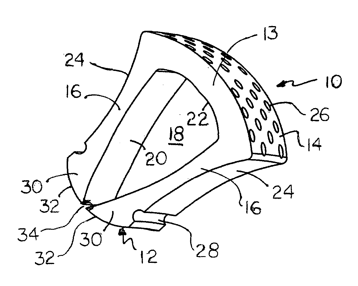
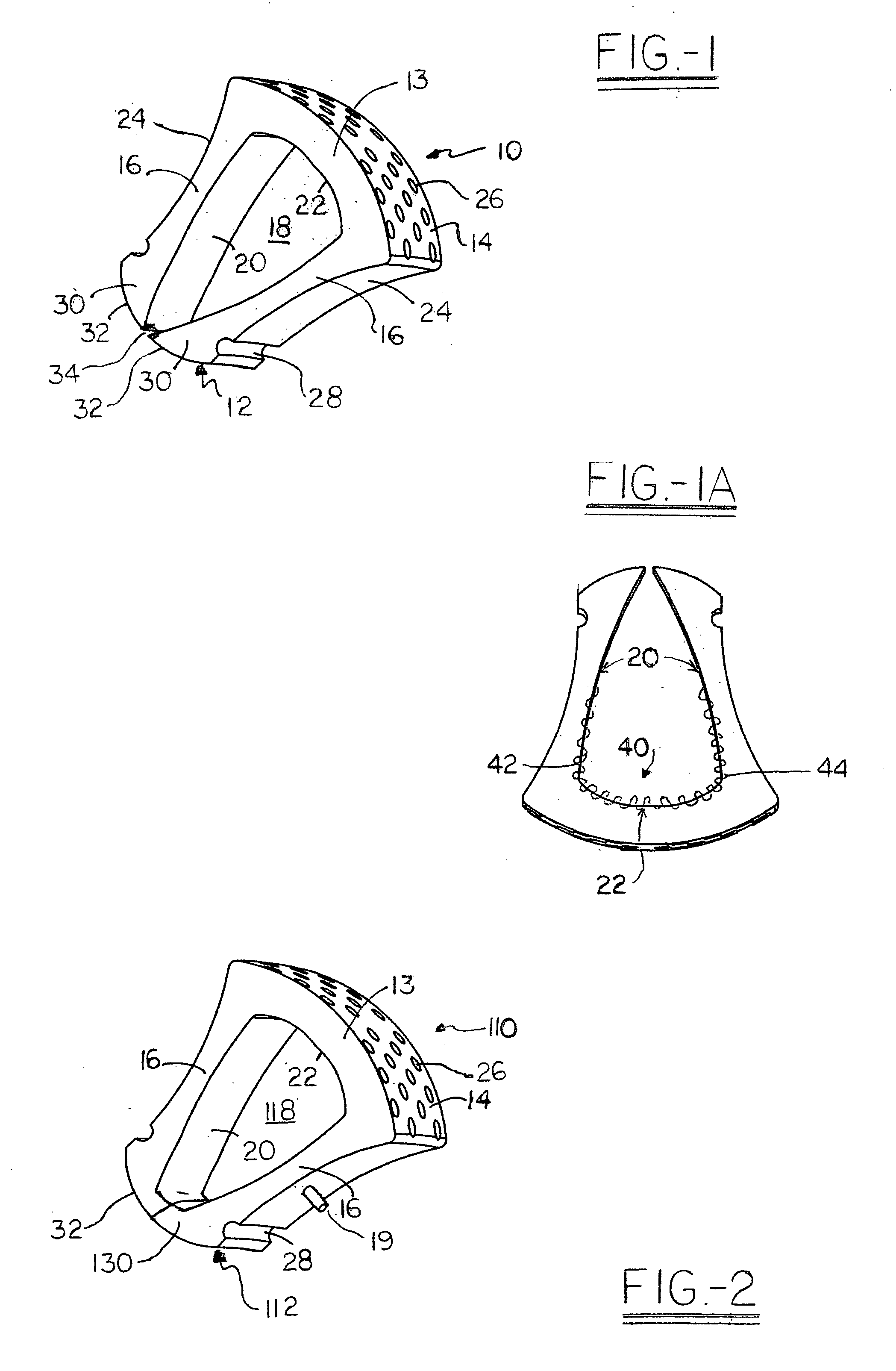
[0019] A first embodiment tire 10 of the present invention is shown with a section thereof in perspective view in FIG. 1. As will be readily understood, the tire 10 is an integral toroidal body with significant symmetries, so there is no need to illustrate the remainder of the tire when shown in diametrical section. The tire 10 has several characteristic features which are readily observed in FIG. 1. Particularly, the tire 10 is formed as a wedge-shaped body in cross-section, with a width that increases as the radial distance from the center of the torus increases. This means that a set of rim-engaging surfaces 12 are narrower in width than the width of a cross or tread member 13 on which is one or more road engaging surfaces 14. It should be understood that reference to a road engaging surface 14 may also relate to engaging surfaces other than roads, for vehicles which are not used on road surfaces. Between the rim-engaging surfaces 12 and the road-engaging surfaces 14 are a pair o...


PUM

PropertyMeasurementUnit
inflation pressuresaaaaaaaaaa
structurally stableaaaaaaaaaa
thicknessaaaaaaaaaa

Abstract

The present invention is directed at a tire design, which allows for proper operational characteristics in all operating conditions, and is not dependent on pneumatic pressurization. The tire is mounted in a wheel rim, and comprises an integral homogeneous toroidal body having a pair of spaced-apart radially extending sidewalls and a cross member. Each sidewall has a first and a second end and an internal face and an external face, with the second end of each of the sidewalls integrally merging into the cross member. A set of rim-engaging surfaces at the first end of each of the sidewalls allows effective mounting to conventional tire rims. An annular chamber is defined by the internal faces of the sidewalls and an internal top wall on the cross member opposite the at least one road engaging surface. The set of rim-engaging surfaces includes a lobe-like portion at the first end of each of the sidewalls, the respective lobe-like projections may be separable when the tire is not mounted on the rim, but being compressed into engagement when the tire is mounted in the rim, thereby closing the annular chamber, or integral with one another to form the enclosed chamber.

Description

RELATE BACK [0001]“This application is a continuation of copending application application Ser. No. 09 / 849,854 filed on May 4, 2001.”[0002] The present invention relates to a tire construction, which utilizes characteristics of the elastomeric tire shell construction without requiring internal pneumatic pressure as the primary performance determinant, the shell having an effectively homogeneous composition and providing a closed toroidal structure. The shell provides an anisotropic or isotropic assembly when mounted in a wheel rim. BACKGROUND OF THE INVENTION [0003] Vehicle tires, especially those for automobiles, motorcycles, bicycles and other vehicles, generally comprise a pressure-containing shell. The shell is seated in a sealing manner onto a wheel rim in order to convert an open chamber in the tire interior into a pressure-retaining closed chamber. The tire supports the load by inflation pressure placing the unloaded shell portion into tension. To provide the pressure-retaini...

Claims


Application Information

Patent Timeline
Patent Type & Authority Applications(United States)
IPC IPC(8): B29C45/00B29D30/00B60C3/02B60C7/10B60C7/12B60C7/24
CPCB29C45/00B29D30/00B60C3/02B60C7/10Y10T152/10504B60C7/24Y10T29/49494Y10T152/10756Y10T152/10747B60C7/12
Inventor CHROBAK, DENNIS S.CHROBAK, JAMES A.
Owner CHROBAK DENNIS S
Learn More