Heat sink assembly and connecting device

Inactive Publication Date: 2005-04-07
AAVID THERMALLOY
View PDF11 Cites 44 Cited by
  • Summary
  • Abstract
  • Description
  • Claims
  • Application Information

AI Technical Summary

Benefits of technology

[0014] In yet another embodiment, the cup member is eliminated and a conical tension spring is used. A coil at the big end of the spring bears against a bearing surface surrounding the aperture on the top surface of the base plate, and a shoulder on the fastener engages a co

Problems solved by technology

The height available after installation of the compressed spring and the head of the push pin above the base

Method used


Image

  • Heat sink assembly and connecting device
  • Heat sink assembly and connecting device
  • Heat sink assembly and connecting device

Examples


first embodiment

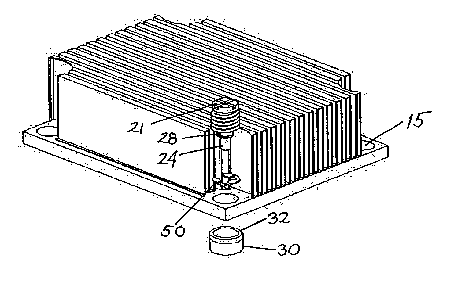
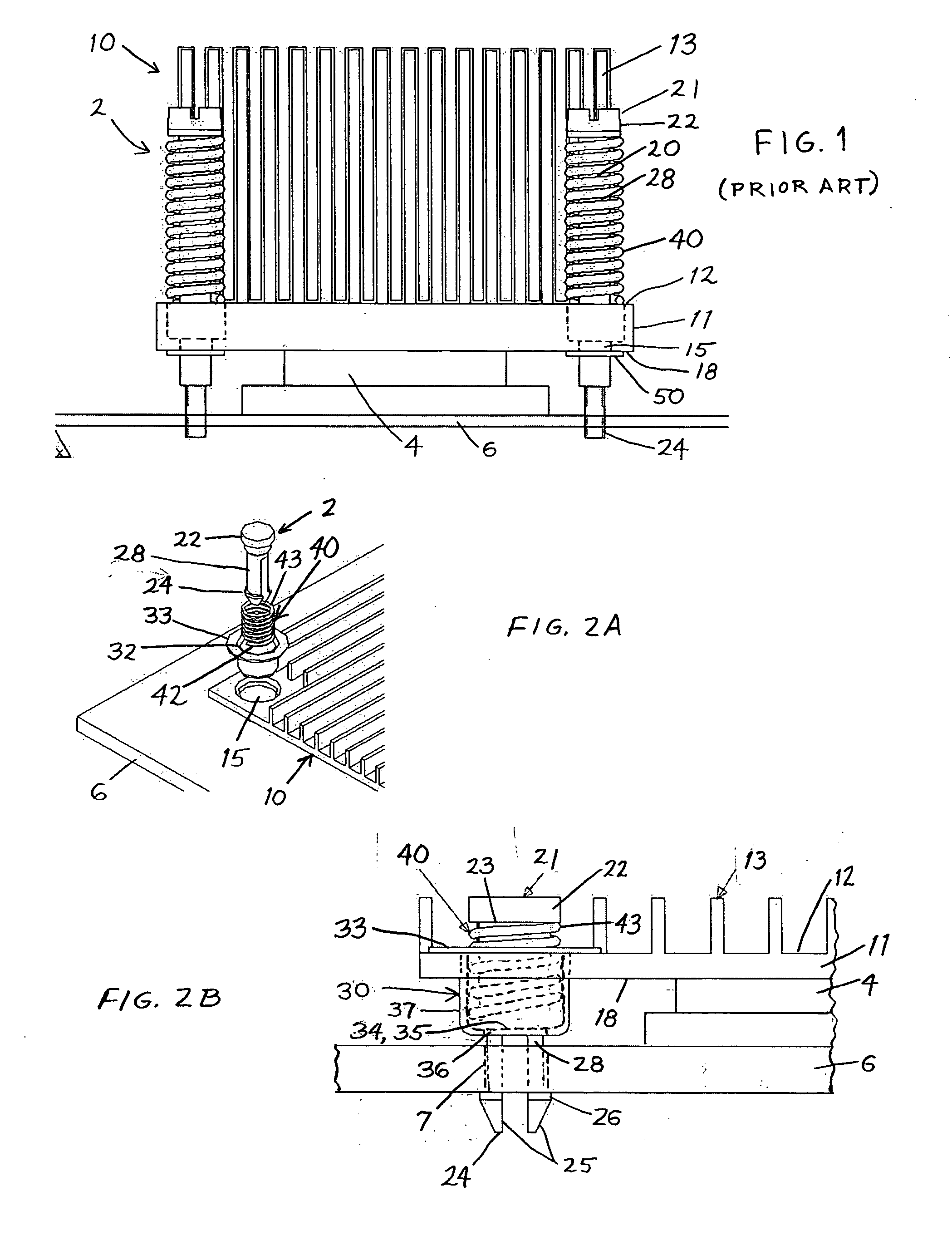
[0024]FIGS. 2A and 2B show connecting device 2 for fastening a heat sink 10 against an electronic device 4 mounted to a printed circuit board 6. The heat sink 10 includes a base plate 11 having a top surface 12 provided with fins 13 which are interrupted around a mounting aperture 15. The opposed bottom surface 18 is received against the electronic device 4. The heat sink is preferably made of aluminum, copper, graphite, or thermally conductive plastic, and may be extruded, machined, cast, or molded.

[0025] The connecting device 2 includes a mechanical fastener 20, a cup member 30, and a spring 40. The mechanical fastener 20 has a first end 21, a second end 24, and a shank 28 extending between said ends. The first end 21 is provided with a head 22 which forms a shoulder 23 facing the second end 25. The second end 24 is provided with resilient mounting prongs 25 having barbs 26 which engage the printed circuit board 6. The fastener may be made of steel, brass, or aluminum, but may als...

second embodiment

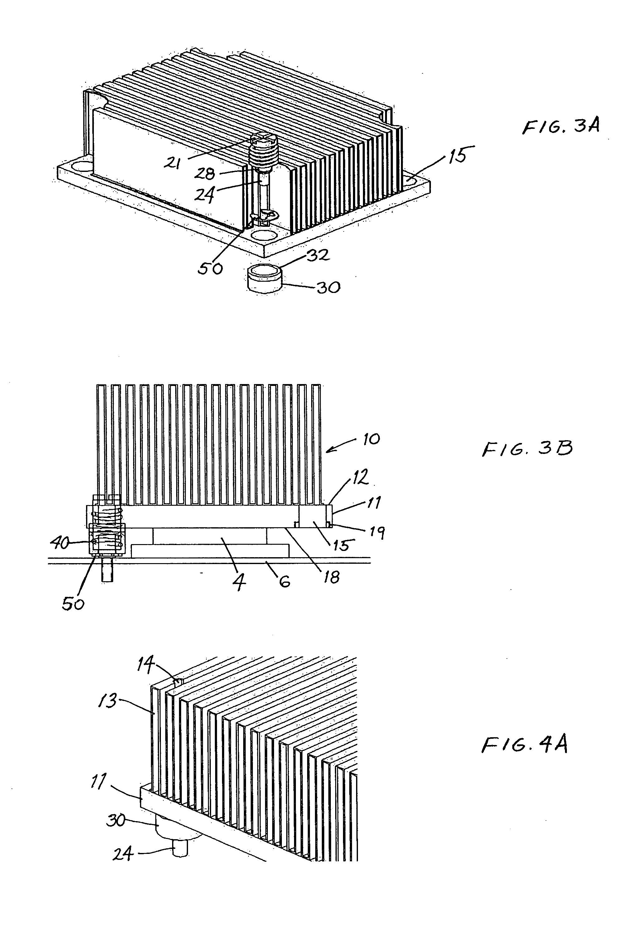
[0029]FIGS. 3A and 3B show the connecting device 2, wherein the cup member 30 is not provided with a flange around the lip 32. Rather, the bottom surface 18 of the heat sink base plate 11 is provided with a countersink 19 around the aperture 15, and the lip 33 is fit into the countersink 19. Alternatively, the cylindrical wall 37 of the cup member 30 may be provided with a shoulder which limits travel in aperture 15 in the base plate 11. The cup member 30 may be press fit, threaded, soldered, brazed, glued, or otherwise attached to the bottom surface of the base plate. The features of the fastener 20 and spring 40 are essentially as described in conjunction with the embodiment of FIGS. 2A and 2B. A retainer 50 in the form of a C-clip is provided to hold the fastener 20, cup member 30, and spring 40 together as a unit which may be pre-assembled to the heat sink 10 prior to assembling to the PCB 6.

third embodiment

[0030]FIGS. 4A and 4B show connecting device which is substantially similar to the second embodiment, but modified for use with an alternative printed circuit board 6 having an aperture 15 which is substantially closed at the top surface 12. Here the shank 28 and spring 40 are somewhat shorter than in the connecting device used with the heat sink 10 of FIGS. 2A and 2B. The first end 21 of the fastener is located in a pocket below the top surface and accessible only via an access hole 16 located centrally of the aperture 15. The advantage here, is that the heat sink fins 13 need not be interrupted above the connector, which can be accessed by a tool received between the fins 13. The fins may, however, be provided with at least one notch 14 to provide sufficient clearance for the tool, which may be a hex key.


PUM


Abstract

A heat sink assembly includes a heat sink with a base plate having a top surface with fins for dissipating heat and an opposed bottom surface for placing against an electronic device mounted on a printed circuit board, and at least one connecting device for loading the heat sink against the electronic device. The connector includes a mechanical fastener such as a push pin having an end which engages the circuit board, a compression spring received against a shoulder on the fastener, and a cup member which is installed in an aperture in the base plate so that a floor of the cup member provides a bearing surface for the spring which is below the bottom surface of the base plate. An alternative connector utilizes a conical spring received through the base plate and receiving the fastener therein to load the spring in tension against the electronic device.

Description

PRIORITY CLAIM [0001] This application claims priority under 35 U.S.C. §119 from U.S. Provisional Application Ser. No. 60 / 508,460, filed Oct. 3, 2003.BACKGROUND OF THE INVENTION [0002] 1. Field of the Invention [0003] The invention relates to an assembly of a heat sink and a connecting device for mounting to an electronic package on a printed circuit board, wherein the connecting device includes a fastener and a spring which loads the heat sink against the electronic device when the fastener is attached to the printed circuit board. [0004] 2. Description of the Related Art [0005] U.S. Pat. No. 5,384,940 discloses a heat sink assembly of this type, wherein the heat sink has a top surface provided with fins and a through hole which receives the shank of a “push pin” fastener having a first end provided with a head, and a second end provided with prongs which engage a hole in a printed circuit board (PCB). A coil spring is provided around the shank between the surface of the printed ci...

Claims


Application Information

Patent Timeline
IPC IPC(8): H01L23/40
CPCH01L23/4006H01L2924/0002H01L2924/00
Inventor WHITNEY, BRADLEY ROBERTKANG, SUKHVINDER SINGH
Owner AAVID THERMALLOY
Why Eureka
Try Eureka