Electric heater with housing

a technology of electric heaters and housings, which is applied in the field of electric heaters, can solve the problems of inconvenient use of electric heaters, troublesome measures to counteract the contact pressure force of resilients, and heaters with a conventional holding frame for modern air conditioners, especially for installation in automotive vehicles, are less and less suited, so as to prevent deflection or bending of the housing, impede the air throughput, and minimize the effect of obstruction

Active Publication Date: 2005-04-07
CATEM
View PDF2 Cites 32 Cited by
  • Summary
  • Abstract
  • Description
  • Claims
  • Application Information

AI Technical Summary

Benefits of technology

[0015] According to an advantageous development of the invention longitudinal struts are provided in addition to the transverse struts in the openings of the housing sides, so that the struts form a grid structure. As a result, the struts as such can be kept particularly thin, so that they will impede the air throughput only insignificantly and nevertheless prevent deflection or bending of the housing in an efficient way.
[0016] To minimize obstruction of the air throughput, the longitudinal struts are particularly arranged such that they are located in the area of the PTC heating elements. Preferably, the housing is made of plastics. An essential advantage of a plastic housing is its small weight, its flexible moldability and its low production costs.

Problems solved by technology

That is why such electric heaters are not suited for use in the case of very small installation heights.
When electric heaters with an exterior holding frame or exterior clamping action are assembled, troublesome measures are needed for counteracting the contact pressure forces of the resilient means / frame that are objectionable during assembly.
Due to these drawbacks heaters with a conventional holding frame for modern air conditioners, especially for installation in automotive vehicles, are less and less suited.
Furthermore, conventional constructions with a holding frame, particularly of metal, have a considerable weight.
A further drawback of metal holder frames is their conductive surface.

Method used


Image

  • Electric heater with housing
  • Electric heater with housing
  • Electric heater with housing

Examples


Embodiment Construction

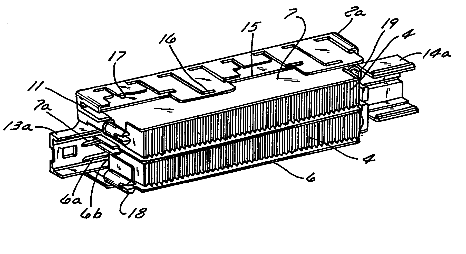
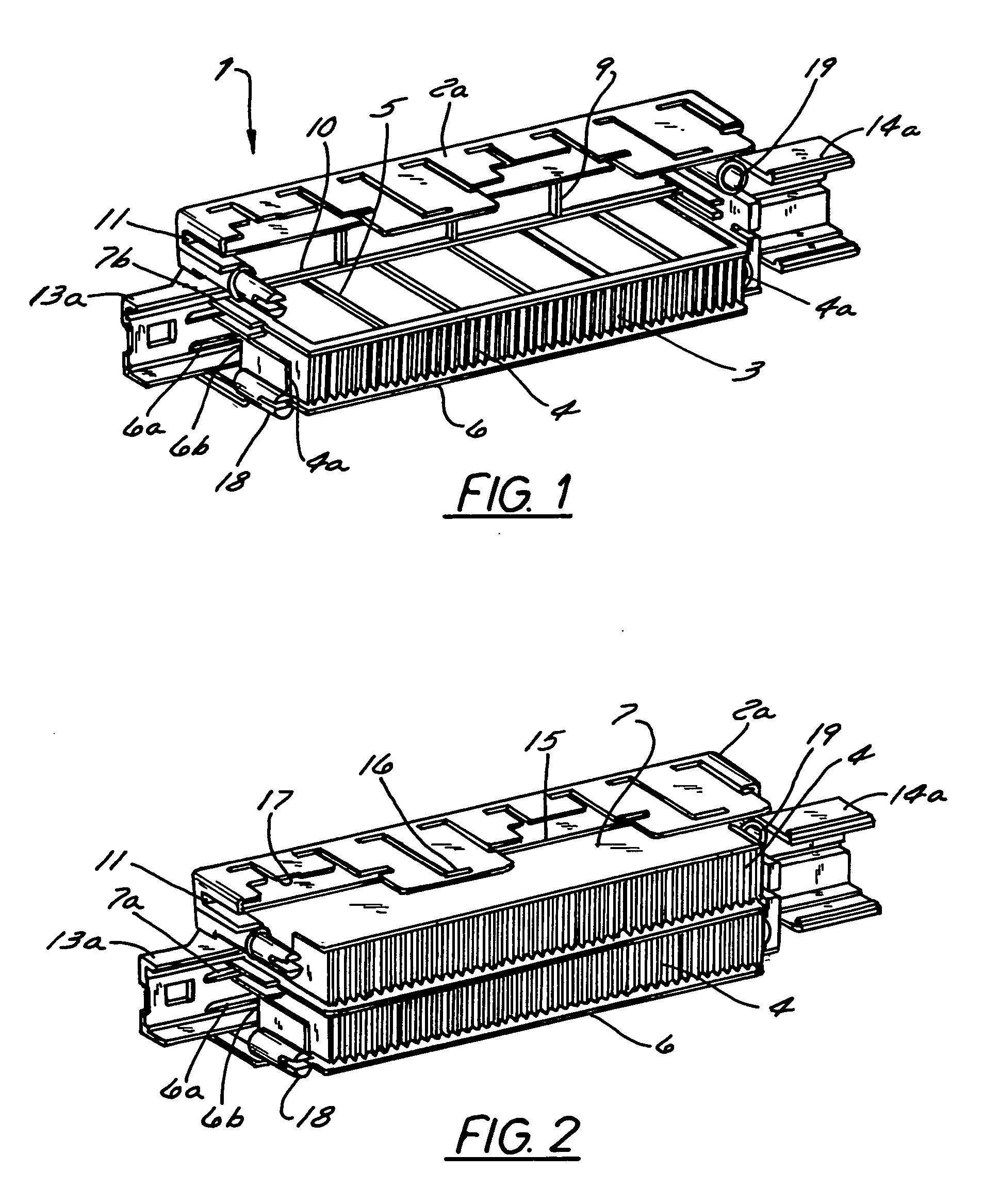
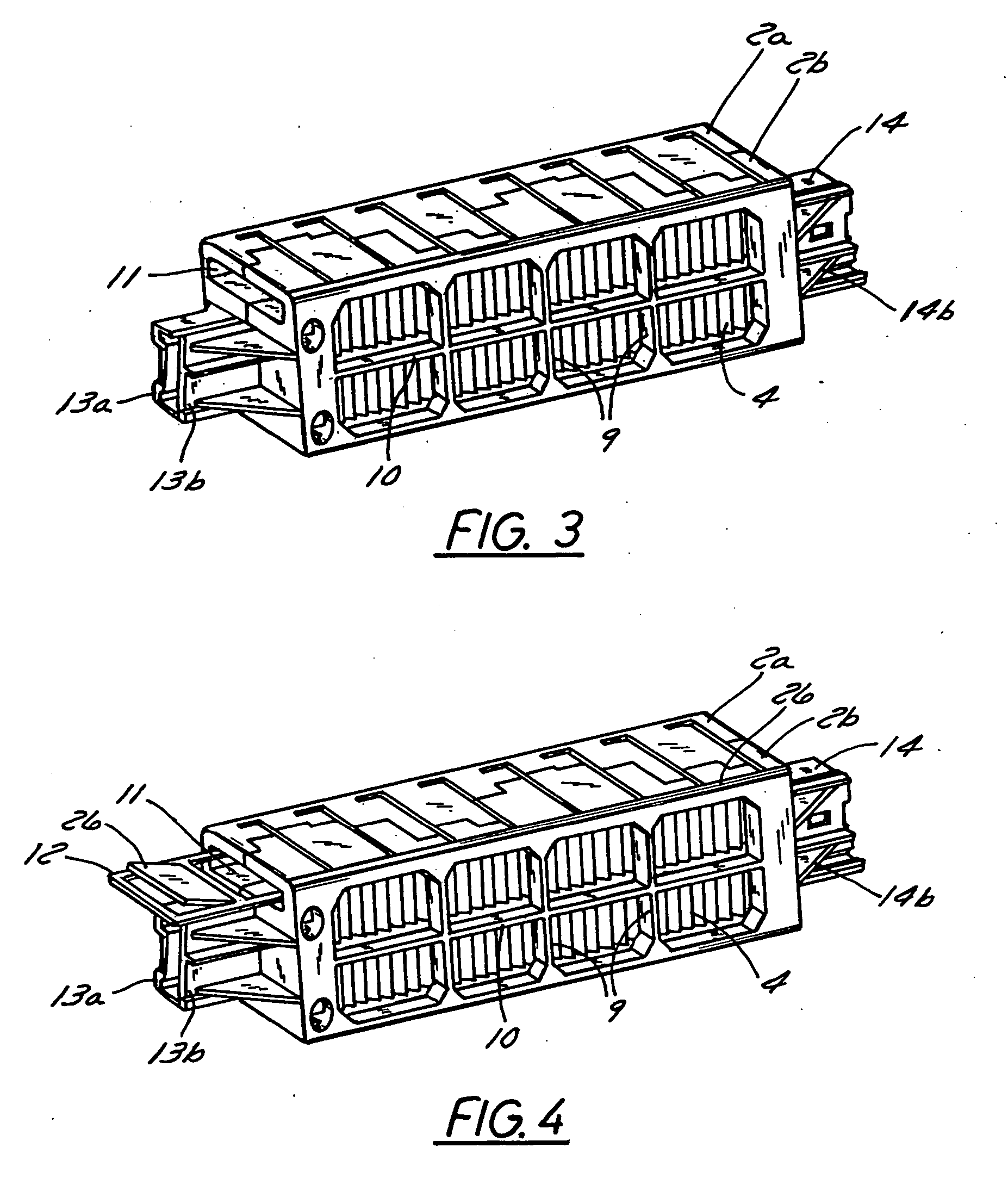
[0047] In contrast to conventional electric heaters for use in automotive vehicles, the heater according to the invention is composed of two half-shells of plastics. During production one housing half can first be equipped in an easy way and the housing is then completed by mounting the second housing half.

[0048] FIGS. 1 to 4 show successive assembling stages of the heater according to the invention, the stages illustrating the structure of the heater according to the invention. FIG. 1 is a perspective view showing one half-shell 2a of half-shells 2a, 2b of the housing. A contact sheet 6, a radiator element 4 and, next thereto, PTC heating elements 3 are inserted into the half-shell 2a. For an easy assembly guide rails and positioning means, respectively, are provided for all components. Especially the position of the contact plate 6 with the contact pin 6a is defined during insertion via guide 6b (and 7b, respectively, for contact plate 7 in FIG. 2). The radiator elements 4 are pr...


PUM


Abstract

The present invention relates to a novel constructional principle for electric heaters, wherein the functions of frame and resilient means are separated from one another. As a frame for an electric heater, a housing is used that consists of two half-shells. Positioning aids for the PTC heating elements are arranged in the housing. The longitudinal sides of the housing are essentially made open to allow for air throughput through the heating register. A resilient device is additionally inserted into the housing, the resilient device compressing the layered structure of radiator elements, PTC heating elements and contact sheets. After the heater has been assembled, the resilient device can be inserted through a lateral opening into the heater.

Description

BACKGROUND OF THE INVENTION [0001] 1. Field of the Invention [0002] The present invention relates to an electric heater, particularly as an auxiliary heating means for an automotive vehicle. [0003] 2. Description of the Related Art [0004] For use in automotive vehicles, particularly automotive vehicles with new, consumption-optimized engines, in which a reduced amount of heat energy is observed, electric auxiliary heaters are used for heating passenger compartment and engine. Such electric heaters are however also suited for other purposes, e.g. in the field of building installations, particularly air conditioning, in industrial plants, or the like. [0005] Preferably, PTC heating elements with radiator elements in heat-conducting communication are used for such an electric auxiliary heater for an automotive vehicle. The heat generated by the PTC heating elements is discharged via the radiator elements to the air flowing therethrough. The total assembly consisting of a layered struct...

Claims


Application Information

Patent Timeline
Patent Type & Authority Applications(United States)
IPC IPC(8): B60H1/03H05B3/06B60H1/22F24C7/00F24H3/04F24H9/18H05B3/14H05B3/50
CPCB60H1/2225B60H2001/2278F24H3/0405F24H3/0429F24H3/0435H05B3/50F24H3/0476F24H9/1818F24H9/1872H05B3/14F24H3/0464F24C7/00
Inventor BOHLENDER, FRANZ
Owner CATEM
Why Eureka
Try Eureka