Underwater electric generator

Inactive Publication Date: 2005-04-07
DUDLEY MAURICE
View PDF2 Cites 18 Cited by
  • Summary
  • Abstract
  • Description
  • Claims
  • Application Information

AI Technical Summary

Benefits of technology

[0003] The present invention is directed to overcoming one or more of the problems set forth above. Briefly summarized, according to one aspect of the invention, an underwater electrical generator comprises an electrical generator and first and second cylinders. Each cylinder has a water inlet and a water outlet. A control device controls t

Problems solved by technology

Once a power plant is constructed, one of the most costly aspects of operation is the fuel cost.
Coal, oil and natural gas are costly, and nuclear fuel is both costly and hazardous.

Method used


Image

  • Underwater electric generator
  • Underwater electric generator

Examples


Embodiment Construction

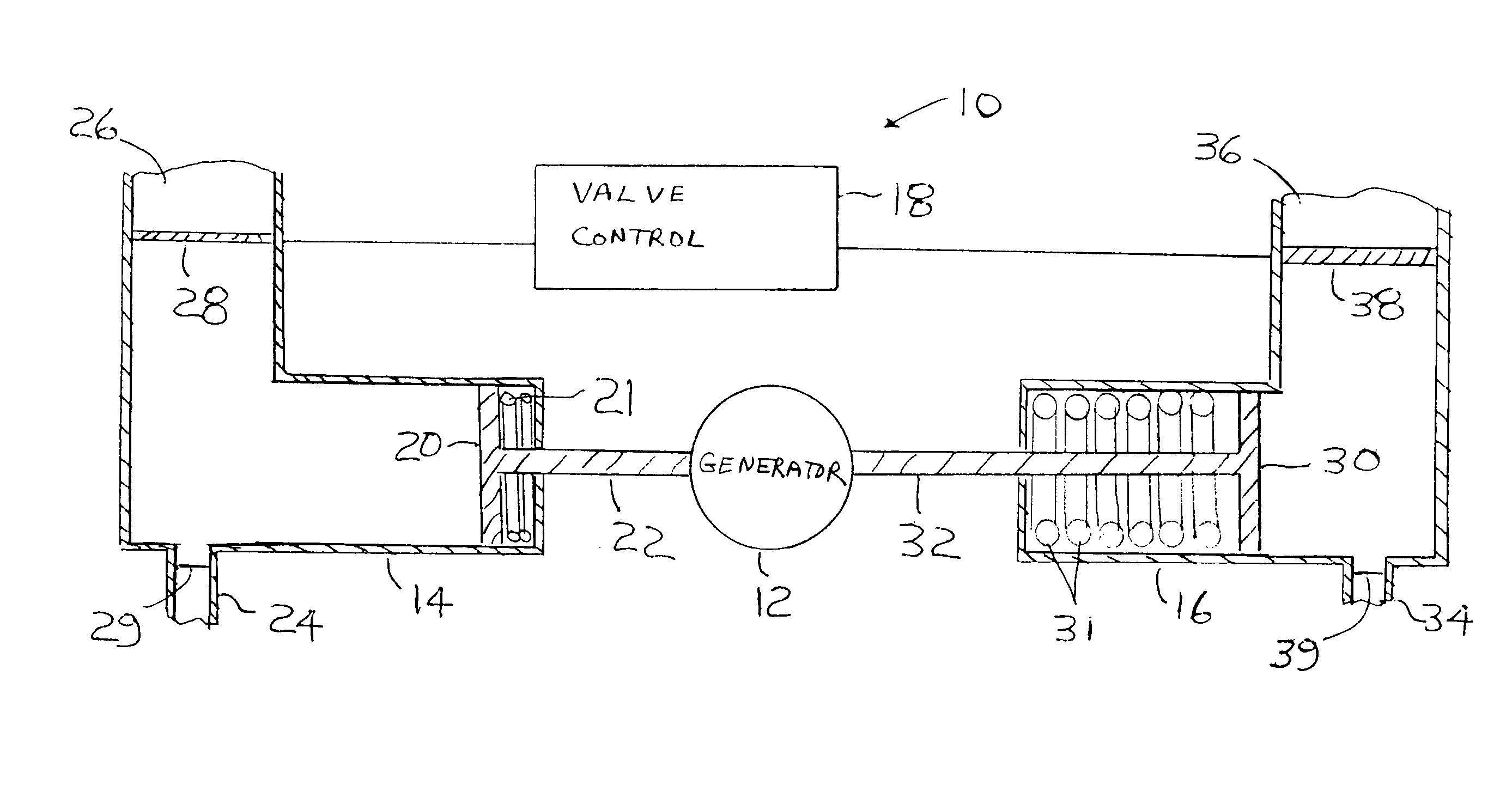
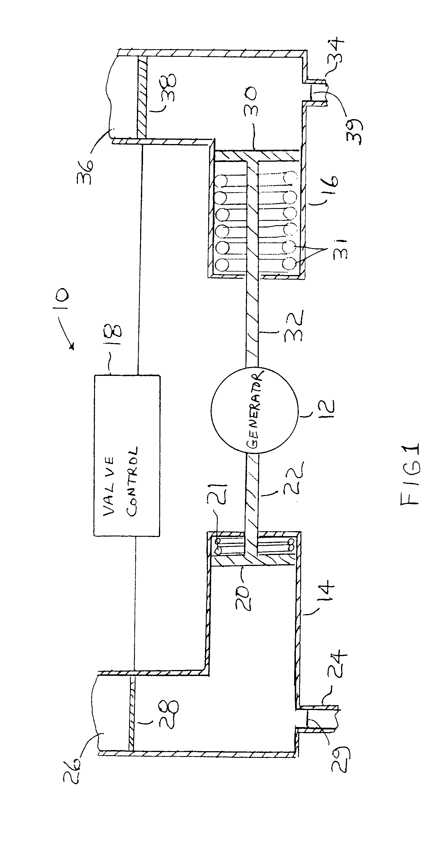
[0006] Referring to the drawing, a submerged system 10 for generating electricity includes a generator 12, first and second cylinders 14, 16 and valve controls 18. The system 10 uses the pressure of a static body of water to turn the generator 12 to produce electricity. The deeper the system is submerged, the greater the water pressure and the greater the amount of electricity that can be generated.

[0007] The first cylinder 14 has a reciprocating piston 20 with a rod 22 attached thereto with the rod 22 coupled to the generator 12 by appropriate gearing to turn the generator in one direction, clockwise, for example. Piston 20 is preferably equipped with a coil spring 21 which biases piston 20 toward a retracted position of rod 22. First cylinder 14 preferably has a horizontal portion which houses piston 20 and water outlet 24, and a vertical portion which houses water inlet 26. Water inlet 26 is equipped with a valve 28 to control egress of water to piston 20, and water outlet 24 is...


PUM


Abstract

An underwater electrical generating system has an electrical generator and first and second cylinders. Each cylinder has a water inlet and a water outlet. A valve control meters the water flow through the water inlet and water outlet. Each cylinder as a reciprocating piston with a rod that turns the generator to produce electricity. Static water pressure is present in the cylinders when the cylinders are submerged and is used to force the pistons to turn the generator to produce electricity.

Description

TECHNICAL FIELD OF THE INVENTION [0001] This invention relates to generation of electricity, and, more particularly, to a method and apparatus for underwater electric generation using static water pressure. BACKGROUND OF THE INVENTION [0002] It is desirable to have low cost electrical power. Once a power plant is constructed, one of the most costly aspects of operation is the fuel cost. Coal, oil and natural gas are costly, and nuclear fuel is both costly and hazardous. Hydroelectric generation has virtually no fuel cost. Hydroelectric generators typically employ the kinetic energy of moving water to generate electricity which requires a moving stream of water provided by either an actual moving stream of water or a gravity fed column of water that turns blades of a turbine. It will be appreciated that it would be highly desirable to generate electricity using static bodies of water which are generally more plentiful or can be economically constructed. SUMMARY OF THE INVENTION [0003...

Claims


Application Information

Patent Timeline
IPC IPC(8): F03B13/00F03B17/02H02P9/04
CPCY02E10/20F03B17/025
Inventor DUDLEY, MAURICE
Owner DUDLEY MAURICE
Why Eureka
Try Eureka