Laminated body of motor and manufacturing method thereof

a technology of laminating body and motor, which is applied in the direction of dynamo-electric machines, electrical apparatus, magnetic circuit shapes/forms/construction, etc., can solve the problems of low material yield, and many production hours consumed on welding and cooling. , to achieve the effect of reducing the cogging torque in the operation of the motor, avoiding thermal deformation, and improvising productivity

Active Publication Date: 2005-04-07
LG ELECTRONICS INC
View PDF10 Cites 42 Cited by
  • Summary
  • Abstract
  • Description
  • Claims
  • Application Information

AI Technical Summary

Benefits of technology

[0012] Therefore, an object of the present invention is to provide a laminated body of a motor and its manufacturing method capable of reducing cogging torque in operation of a motor, making no thermal deformation and improvising productivity.

Problems solved by technology

However, yield of materials is low.
First, in coupling of the laminated body 10 by means of welding, a defective measurement may occur due to deformation by heat generated in welding, equipment for welding and cooling is required, and many production hours are consumed on welding and cooling.
In addition, the welding processing causes a change of material in quality due to heat, whereby generation of flux in operation of the motor may be interrupted.
Besides, another main problem is that cogging torque is generated by interaction between the laminated body 10 and a permanent magnet.
However, this method has a limit in that, in case of automatically winding a winding coil, the minimum passage of a winding nozzle for automatic winding should be provided.

Method used


Image

  • Laminated body of motor and manufacturing method thereof
  • Laminated body of motor and manufacturing method thereof
  • Laminated body of motor and manufacturing method thereof

Examples


Embodiment Construction

[0028] Reference will now be made in detail to the preferred embodiments of the present invention, examples of which are illustrated in the accompanying drawings.

[0029] A spirit of the present invention may be modified to be used for a rotary motor, such as a BLDC motor, and a linear motor or the like.

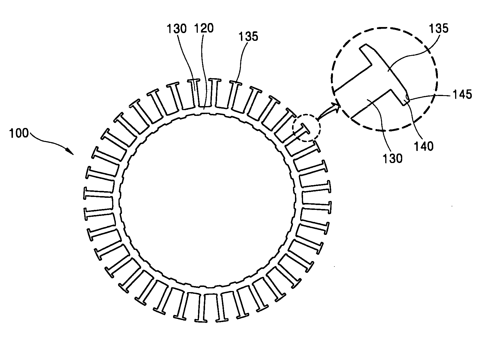
[0030]FIGS. 3A and 3B are plan views of a laminated body of a motor according to the first embodiment of the present invention.

[0031] As shown, the laminated body 100 of the motor according to the present invention includes: a yoke part 120 having a belt shape with a long length in comparison with its width and spirally laminated to form a hollow cylindrical shape; a plurality of teeth parts 130 protruding from one side edge of the yoke part 120 in a width direction and disposed along a longitudinal direction in an isolated manner at predetermined intervals; a stopping protrusion 135 extendingly formed at a protruding end of each teeth part 130 in a longitudinal direction of the yok...


PUM

PropertyMeasurementUnit
lengthaaaaaaaaaa
widthaaaaaaaaaa
cogging torqueaaaaaaaaaa

Abstract

A laminated body of a motor includes: a yoke part having a belt shape with a long length in comparison with its width and spirally laminated to form a hollow cylindrical shape; a plurality of teeth parts protruding from one side edge of the yoke part in a width direction and disposed along a longitudinal direction in an isolated manner at a predetermined distance; a stopping protrusion extendingly formed at a protruding end of the teeth part in a longitudinal direction of the yoke part; and an inclined portion having an inclined surface formed by decreasing a width of the stopping protrusion toward its end so as to reduce cogging torque, so that a minimum passage for a winding nozzle is provided while cogging torque is reduced. A laminated body of a motor includes: a yoke part having a belt shape with a long length in comparison with its width and spirally laminated to form a hollow cylindrical shape; a plurality of teeth parts protruding from one side edge of the yoke part in a width direction and disposed along a longitudinal direction in an isolated manner at a predetermined distance; and a protrusion receiving groove recessed in one side of the teeth part along a thickness direction and a coupling protrusion protruding from its other side along the thickness direction of the teeth part to be inserted and fixed by each other, so that defective measurement and an increase in production time caused by welding operation are prevented.

Description

BACKGROUND OF THE INVENTION [0001] 1. Field of the Invention [0002] The present invention relates to a laminated (stacked) body of a motor, and particularly, to a laminated body of a motor and its manufacturing method capable of reducing cogging torque in operation of the motor, making no thermal deformation and improving productivity. [0003] 2. Description of the Background Art [0004] A conventional motor laminated body of this type is manufactured by stacking a plurality of ring-shaped board members blanked directly from a steel board, as disclosed in JP 57-100823, for instance. However, yield of materials is low. For this reason, JP 57-75551 discloses a method for improving the yield in such a manner that a belt-shaped board member with a large number of teeth is spirally wound and undergoes plastic deformation, and several layers are fastened by welding the respective layers. [0005] In FIGS. 1 and 2, another laminated body, which has a similar structure to the above-mentioned st...

Claims


Application Information

Patent Timeline
Patent Type & Authority Applications(United States)
IPC IPC(8): H02K1/18H02K15/02
CPCH02K1/185Y10T29/49009H02K15/026H02K1/187
Inventor LEE, SEUNG-WEON
Owner LG ELECTRONICS INC
Why Eureka
Try Eureka