Integrated Anti-differential current sensing system

a technology of anti-differential current and sensing system, which is applied in the field of current measurement and monitoring, can solve the problems of many inherent limitations, inapplicability of dc applications, and inability of shunt-type sensors to adapt to alternating current applications

Active Publication Date: 2005-04-07
EATON INTELLIGENT POWER LTD
View PDF6 Cites 57 Cited by
  • Summary
  • Abstract
  • Description
  • Claims
  • Application Information

AI Technical Summary

Benefits of technology

[0015] The present invention is directed to a system and method that overcomes the aforementioned drawbacks. Specifically, an anti-differential, error correcting, sensor topology is utilized that eliminates the need for ferromagnetic concentrators. As such, the sensor eliminates the limitations associated with metal-core based current sensors and is capable of providing accurate current monitoring in the presence of external magnetic fields. Furthermore, the sensor is configured to communicate with a variety of systems and subsystems, such as communications interfaces, breaking and tripping systems, and the like.
[0018] In accordance with another aspect, the invention includes a current sensing system that includes a conductor configured to conduct a current flow therethrough and a housing configured to be mounted to the conductor. A first Hall effect sensor is configured to be fixed within the housing and to provide a first indication of current flow through the conductor and a second Hall effect sensor is configured to be fixed within the housing and to provide a second indication of current flow through the conductor. A processing component is configured to receive the first indication of current flow and the second indication of current flow and calculate at least one of a sum and a difference of the first indication of current flow and the second indication of current flow to generate an anti-differential output that reduces errors generated by magnetic fields induced thereon from sources external from the conductive path.

Problems solved by technology

Contact sensors are common in many circumstances but include many inherent limitations.
For example, while shunt-type sensors are readily applicable to direct current (DC) applications, shunt-type sensors are not suited to alternating current (AC) applications due to errors caused by induced loop voltages.
On the other hand, while current transformers (CT) are suited for AC applications, such are inapplicable to DC applications due to the fundamental nature of transformers.
In any case, these contact-based sensor systems are typically large and may be difficult to employ, especially in areas where tight size constraints are necessary.
Therefore, should the operating conditions lead to the saturation of the metal core, inaccurate current measurements may be gathered.
Accordingly, sensing ranges of metal core sensors are typically hard-limited to the “near-linear” operational range.
Additionally, sensors relying on metal cores can experience hysteresis in the metal core that may produce a zero current offset error.
As such, zero offsets are particularly troublesome when monitoring DC power systems.
As all permeable ferromagnetic materials exhibit some level of hysteresis, which produces an error at zero current, metal core sensors are susceptible to erroneous current measurements at low or no current levels.
Furthermore, while electronic-based sensors are typically limited by the voltage rails used in the sensor output stages, current sensors employing metal cores have an additional limitation imposed by the saturation point of the material.
However, these systems merely diminish the effects of the errors, and do not entirely eliminate the potential for errors and incorrect current readings.
However, while the removal of the metal core eliminates the potential for inaccurate current measurements due to metal core saturation, hysteresis, or eddy currents, the air core does not have the magnetic flux magnifying or concentrating effect of metal cores.
Therefore, air-core current sensors are readily susceptible to influence by external magnetic fields and may provide inaccurate current measurements.
As such, air-core sensors are typically unsuitable for applications where multiple high external magnetic fields are present.
As an overwhelming percentage of current sensors are required to be deployed in areas where numerous conductors and corresponding magnetic fields are in close proximity, air-core sensors are often undesirable.

Method used


Image

  • Integrated Anti-differential current sensing system
  • Integrated Anti-differential current sensing system
  • Integrated Anti-differential current sensing system

Examples


Embodiment Construction

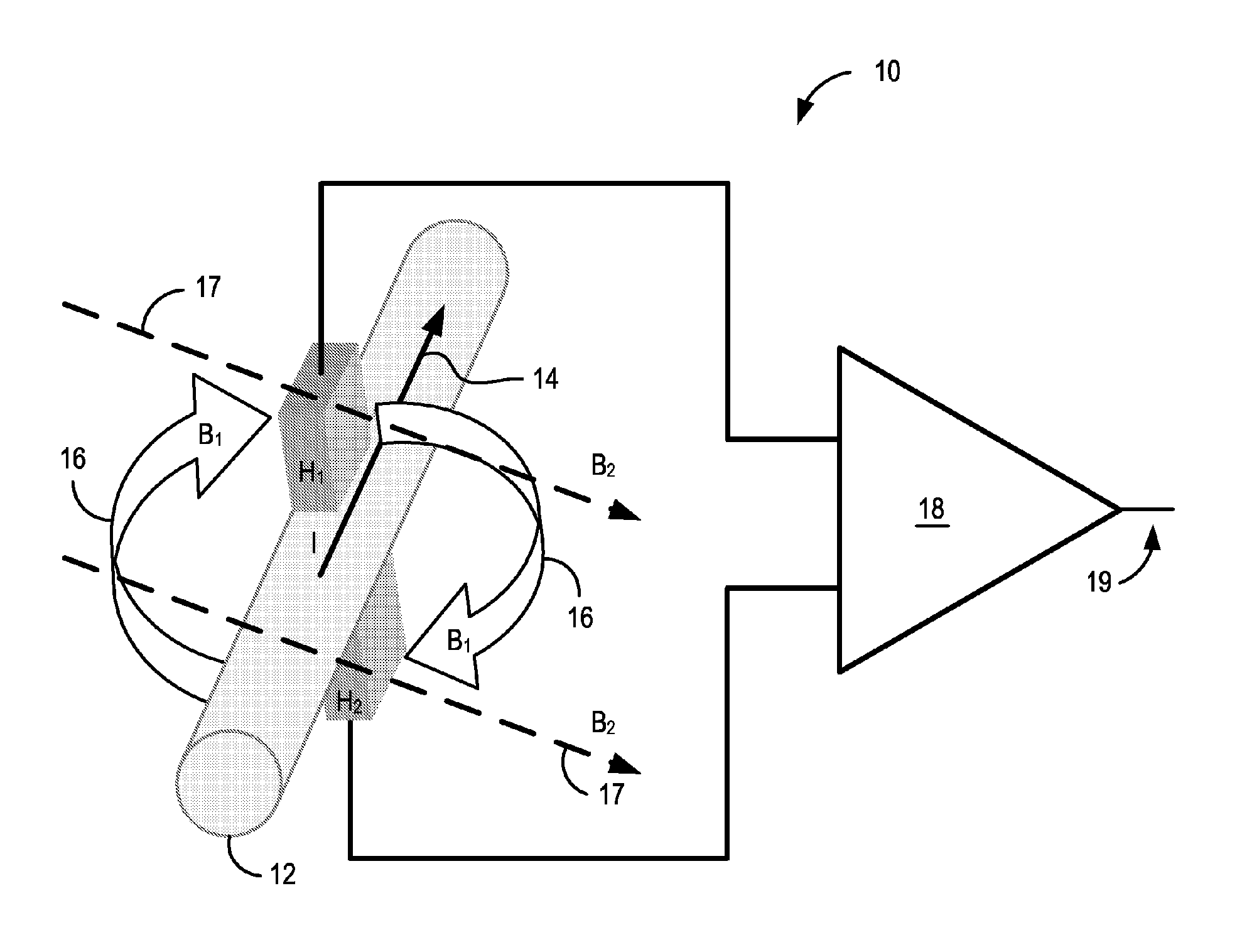
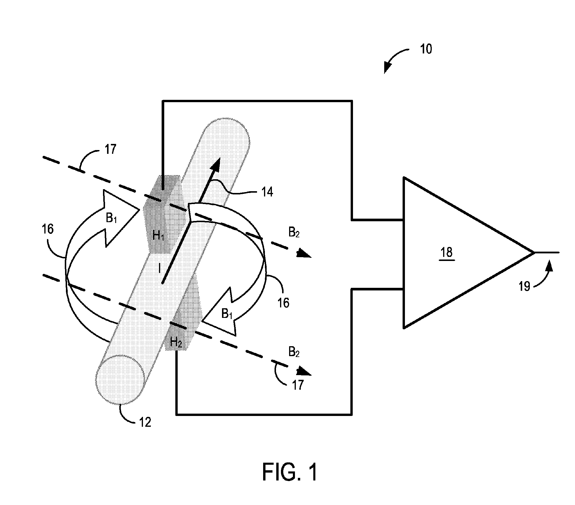
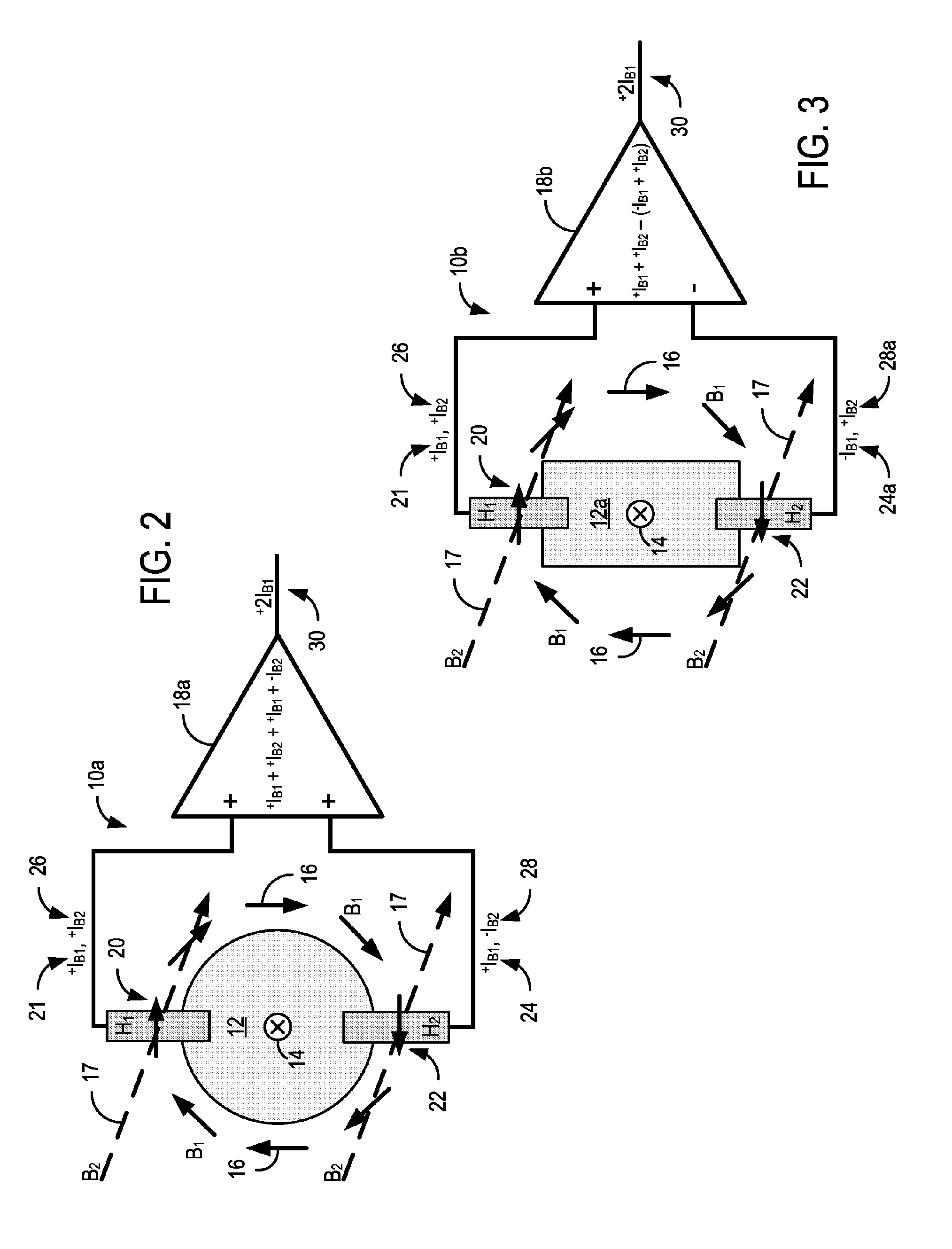
[0034] The present invention is related to a system and method for anti-differential, error-correcting current sensing. A plurality of magnetic flux sensors is arranged about a conductor and provides feedback to a processing component or device configured to generate an output with reduced feedback induced by magnetic fields external to the conductor. The plurality of magnetic flux sensors may be disposed in geometrically designed recesses configured to amplify the magnetic flux received by the plurality of magnetic flux sensors. The system may be disposed in a variety of configurations designed for optimal disposition of the plurality of magnetic flux sensors about a given conductor type. Some examples of possible configurations include etched spiral path topologies for low current and printed circuit board current sensing, dual-spiral and spiral-helix topologies for contact based current sensing, and wire and bus bar mount topologies for wire and bus bar conductors. Furthermore, t...


PUM


Abstract

The present invention is directed to system for current sensing including a first Hall effect sensor and a second Hall effect sensor constructed to provide feedback indicating current flow through a conductor susceptible to external magnetic flux. A housing is configured to position the first Hall effect sensor and the second Hall effect sensor about the conductor to provide generally magnitude equal feedback of the current flow through the conductor and generally polarity opposite feedback of the external magnetic flux.

Description

CROSS-REFERENCE TO RELATED APPLICATION [0001] This application claims the benefit of prior U.S. Provisional Application Ser. No. 60 / 507,896 filed Oct. 1, 1363 and entitled INTEGRATED, COMMUNICATING, NON-CONTACT CURRENT SENSOR AND ARC FAULT DETECTOR FOR BUS, CABLE AND FEED THROUGH INSTALLATIONS.BACKGROUND OF THE INVENTION [0002] The present invention relates generally to current measuring and monitoring, more particularly, to a system and method for measuring current by sensing magnetic flux associated with current flow through a conductor. A dual Hall sensor configuration arranged according to an anti-differential topology is utilized to sense magnetic flux and provides feedback to a processing component. The processing component is arranged to generate an anti-differential output from the feedback received to remove feedback attributable to magnetic fields induced externally from the conductor. The anti-differential current sensor is disposed in a housing configured to arrange the ...

Claims


Application Information

Patent Timeline
Patent Type & Authority Applications(United States)
IPC IPC(8): G01R15/20
CPCG01R15/207G01R15/202
Inventor HASTINGS, JEROME K.GASS, DALE L.PAHL, BIRGERLEE, DAVIN R.HANSEN, JAMES E.
Owner EATON INTELLIGENT POWER LTD
Why Eureka
Try Eureka