
Dual position linear displacement micromechanism

Inactive Publication Date: 2005-04-07
INTELLECTUAL VENTURES FUND 83 LLC
View PDF13 Cites 30 Cited by
  • Summary
  • Abstract
  • Description
  • Claims
  • Application Information

AI Technical Summary

Benefits of technology

[0014] Another embodiment of the present invention provides for a latching mechanism comprising a grasping member, a lock slider, and a detent slider. The lock slider is configured to induce a locking deflection with respect to the grasping member to reach an engaged position. The lock slider is also capable of inducing an unlocking deflection with respect to the grasping member, where the unlocking deflection is greater than the locking deflection. The detent slider is coupled to the lock slider to selectively maintain the unlocking deflection with respect to the grasping member. This unlocking deflection allows the lock slider to disengage the grasping member and retract to its initial position.

Problems solved by technology

However, most conventional switches are constructed of rigid elements that are connected by hinges, and therefore do not obtain the benefits of compliant technology.
Bistable mechanisms present a unique challenge because the compliant elements must be properly balanced so that two fully stable positions exist.
Even if a bistable design is obtained by fortunate guesswork or extensive testing, conventional optimization techniques are often ineffective because the design space is so complex, i.e., highly nonlinear and discontinuous, with such a small feasible space that gradient-driven methods are unable to reach a workable solution.
The likelihood that a stochastic method will stumble onto a solution is extremely small in fully compliant designs.
Hence, it is difficult to enhance the fully compliant bistable designs, except through additional experimentation.
Unfortunately, previous MEMS bistable designs have encountered difficulties with applying pin joints to non-stationary members.
Additionally, various attempts of using non-stationary pin joints have encountered motion problems as the result of stiction, the bonding of moveable members to the microchip substrate.
Another problem in the art of bistable and dual positional mechanisms is the inability of these mechanisms to sustain a force that is greater than the force that actuates the mechanism into its stable configurations.
Further, complex processes and operations are needed to operate these mechanisms that limit the number of applications for latching mechanisms, especially MEMS applications.
This subsequently increases the cost and size of the mechanism.

Method used


Image

  • Dual position linear displacement micromechanism
  • Dual position linear displacement micromechanism
  • Dual position linear displacement micromechanism

Examples


Embodiment Construction

[0036] The present apparatus and method will be best understood by reference to the drawings, wherein like parts and steps are designated by like numerals throughout. It will be readily understood that the components of the present mechanism, as generally described and illustrated in the Figures herein, could be arranged and designed in a wide variety of different configurations. Thus, the following detailed description of the embodiments of the apparatus and method, as represented in the Figures, are not intended to limit the scope of the claim, but are merely representative of present embodiments of the apparatus and method.

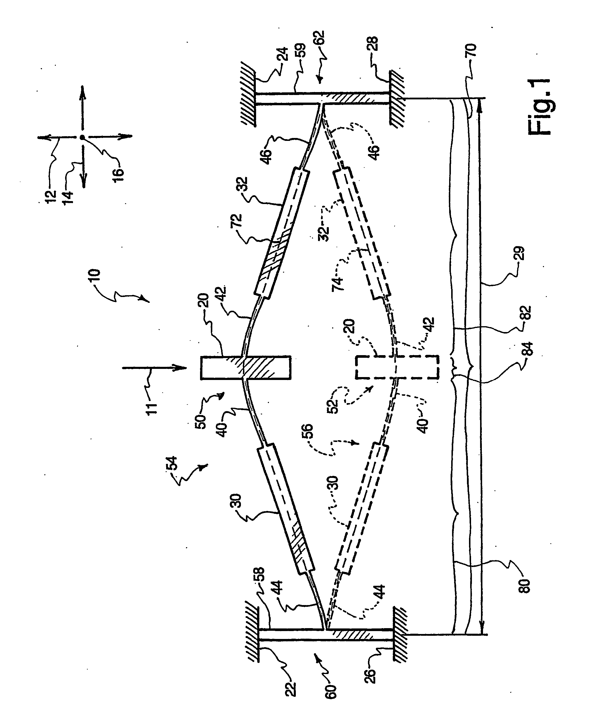
[0037] Referring to FIG. 1, one example of an integrally formed compliant mechanism 10, or mechanism 10, is shown. The mechanism10 may be sized for MEMS applications. Although many of the examples presented herein apply to MEMS applications, the apparatus and method of the present invention are not limited to MEMS, but are rather applicable to compliant mechan...


PUM


Abstract

An apparatus (1) that is capable of a first stable configuration and a second stable configuration is disclosed. The bistable mechanism (10) has a leg (30, 32) that is coupled on one end by a base member (22, 24) and on the other end by a shuttle (20). The leg (30, 32) stores potential energy as it is deflected. The potential energy stored in the leg (30, 32) has a maximum potential energy position with a low potential energy position on either side of the maximum. An apparatus and method are also disclosed for a latching mechanism (910) and the associated method. The latching mechanism (910) is comprised of a grasping member (932), a lock slider (928), and a detent slider (916). These three members (916, 928, 932) operate together to induce a locked configuration and an unlocked configuration by actuating the lock slider (928) in a single direction.

Description

1. FIELD OF THE INVENTION [0001] The present method and apparatus relates to dual position mechanisms. More particularly, the invention relates to compliant bistable mechanisms, and the invention also relates to an apparatus and method for a dual position latching mechanism. 2. TECHNICAL BACKGROUND [0002] The term “compliant mechanisms” relates to a family of devices in which integrally formed flexural members provide motion through deflection. Such flexural members may therefore be used to replace conventional multi-part elements such as pin joints. Compliant mechanisms provide several benefits, including backlash-free, wear-free, and friction-free operation. Moreover, compliant mechanisms significantly reduce manufacturing time and cost. Compliant mechanisms can replace many conventional devices to improve functional characteristics and decrease manufacturing costs. Assembly may, in some cases, be obviated entirely because compliant structures often consist of a single piece of ma...

Claims


Application Information

Patent Timeline
IPC IPC(8): B81B3/00
CPCB81B3/0054B81B3/0062B81B2201/037B81B2203/051B81B2203/053H01H2061/006H01H1/0036H01H61/04H01H2001/0042H01H2001/0047H01H2001/0078H01F2007/068
Inventor HOWELL, LARRYLYON, SCOTTWEIGHT, BRENTCLEMENTS, DEANNE
Owner INTELLECTUAL VENTURES FUND 83 LLC
Learn More