Low-profile, multi-band antenna module

Inactive Publication Date: 2005-04-07
GM GLOBAL TECH OPERATIONS LLC
View PDF18 Cites 20 Cited by
  • Summary
  • Abstract
  • Description
  • Claims
  • Application Information

AI Technical Summary

Benefits of technology

[0007] In other features, a transmission line has a first end that communicates with the first RF multiplexer and transmits the first and second RF signals. A second RF multiplexer communicates with a second end of the transmission line and separates the first and second RF signals. The first and second RF multiplexer implement out-of-band rejection to minimize interference between the first and second RF signals. The first RF signals are transmitted from the second RF multiplexer to a first transceiver and the second RF signals are transmitted from the second RF multiplexer to a second transceiver. At least one of the first antenna and the second antenna communicates with at least one amplifier. The transmission line supplies direct current (DC) power to at least one amplifier.
[0008] In still other features of the invention, the first and second antenna are arranged on the panel in an orientation that minimizes electrical interference between the first and second antenna. A combination of the first and second antenna minimizes interference between the first and second RF band. At least one of the first antenna and the second antenna radiates circular polarization and vertical polarization that is ideal for satellite radio communication. At least one of the first antenna and the second antenna radiates circular polarization that is ideal for global positioning system (GPS) satellite communication. At least one of the first antenna and the second antenna radiates vertical polarization that is ideal for terrestrial communication.

Problems solved by technology

However, it is difficult to make a single receiving element receive multiple bands because each wireless service requires a different radiation pattern.
However, as the number of cables increases, the cost increases.
Additionally, certain combinations of antenna receiving elements can cause interference.
In addition to cost, the overall dimensions of the antenna are important.
A large number of antenna receiving elements increases the size of the antenna module.
As the size increases, the aerodynamic drag increases, which may cause wind noise and / or reduce fuel economy.

Method used


Image

  • Low-profile, multi-band antenna module
  • Low-profile, multi-band antenna module
  • Low-profile, multi-band antenna module

Examples


Embodiment Construction

[0024] The following description of the preferred embodiment(s) is merely exemplary in nature and is in no way intended to limit the invention, its application, or uses. For purposes of clarity, the same reference numbers will be used in the drawings to identify similar elements.

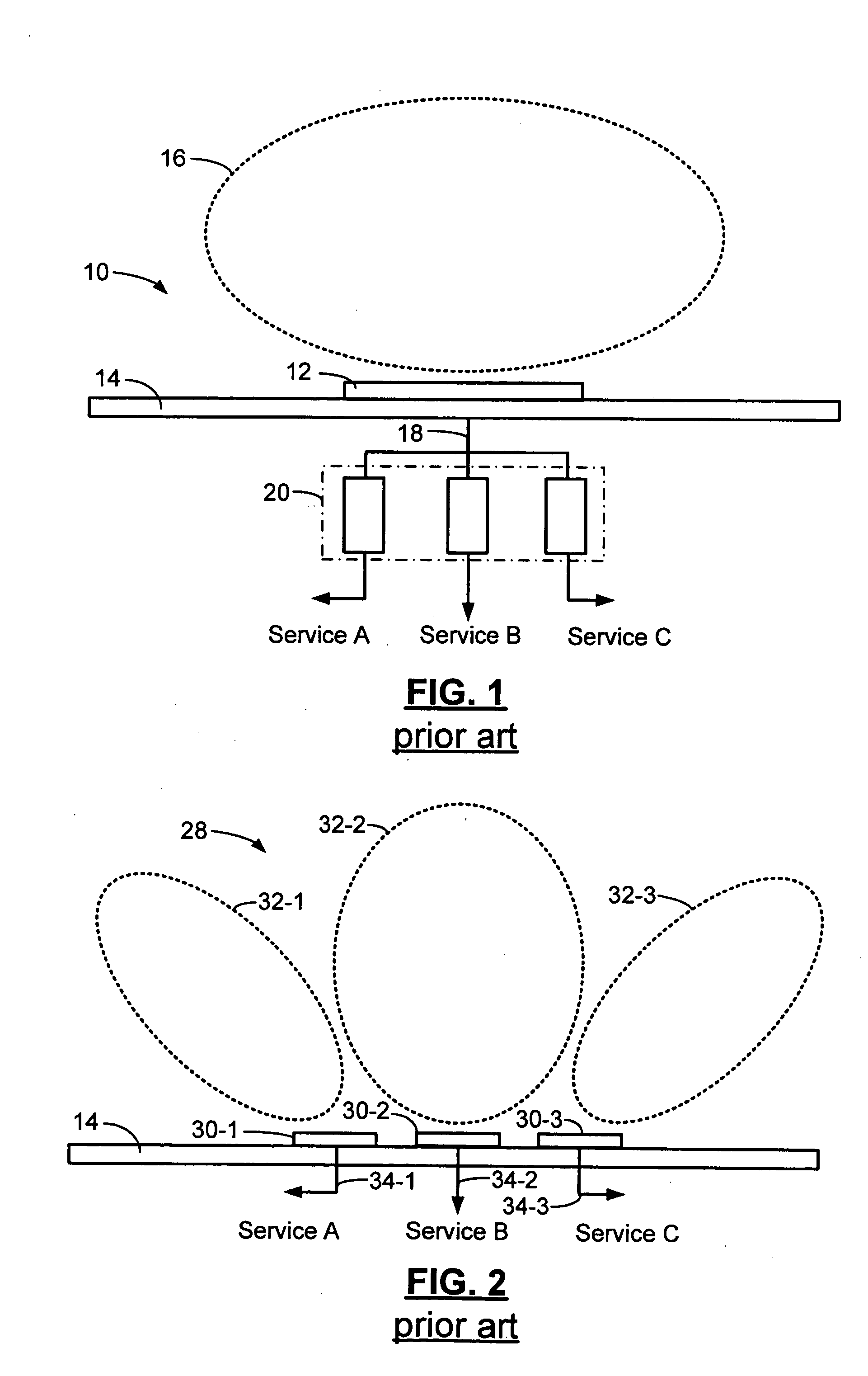
[0025] Referring to FIG. 1, a first prior art multi-band antenna module 10 includes a single receiving element 12 with a broad bandwidth. The single receiving element 12 is mounted on a ground plane 14 and has a broad radiation pattern 16 designed to receive signals from all bands of interest. The received signals are transmitted on a single cable 18 to a set of filter banks 20, where the signals are filtered and distributed to their appropriate receivers. While a single receiving element 12 and a single cable 18 are used, it is difficult for a broad radiation pattern 16 to receive all of the desired signals. Many radio frequency (RF) services require different radiation patterns at specific frequencies.

[0...


PUM


Abstract

A low-profile multi-band antenna module includes first and second antennas that transmit first and second radio frequency (RF) signals in a first and second RF band, respectively. A first RF multiplexer combines the first and second RF signals for transmission. The first antenna, second antenna, and first RF multiplexer are arranged on a panel. A transmission line communicates with the first RF multiplexer and transmits the first and second RF signals. A second RF multiplexer communicates with the transmission line and separates the first and second RF signals. At least one of the antennas communicates with an amplifier. The transmission line supplies direct current (DC) power to the amplifier. The first and second antenna are arranged on the panel in an orientation that minimizes electrical interference between the first and second antenna. A combination of the first and second antenna minimizes interference between the first and second RF band.

Description

FIELD OF THE INVENTION [0001] The present invention relates to low-profile antennas, and more particularly to low-profile antennas with multi-band capabilities. BACKGROUND OF THE INVENTION [0002] Vehicles are receiving an increasing number of wireless services, such as cellular phone service, satellite radio, terrestrial radio, and Global Positioning System (GPS) service. As additional wireless services become available, a vehicle must be equipped to accommodate the different types of signals. Multi-band antennas are widely used in vehicles. When designing multi-band antennas, designers focus on cost, aesthetics, and aerodynamics. [0003] Conventional multi-band antennas have a single receiving element with a broad bandwidth and are designed to receive signals from all bands of interest. However, it is difficult to make a single receiving element receive multiple bands because each wireless service requires a different radiation pattern. [0004] Other multi-band antennas have a single...

Claims


Application Information

Patent Timeline
IPC IPC(8): H01Q1/32H01Q21/30H01Q23/00
CPCH01Q1/3233H01Q23/00H01Q21/30
Inventor SIEVENPIPER, DANIEL F.TANGONAN, GREGORY L.HSU, HUI-PINRILEY, ROBERT M. JR.HANSELMAN, GARY J.
Owner GM GLOBAL TECH OPERATIONS LLC
Why Eureka
Try Eureka