
Projector and light-shielding heat-dissipating mask for the same

a technology of projectors and masks, applied in the field of projectors, can solve the problems of low fan efficiency, high vent temperature, large air flow impedance during heat dissipation process, etc., and achieve the effects of low air flow impedance, good thermal conductivity, and reduced temperature around the air ven

Inactive Publication Date: 2005-04-07
DELTA ELECTRONICS INC
View PDF7 Cites 26 Cited by
  • Summary
  • Abstract
  • Description
  • Claims
  • Application Information

AI Technical Summary

Benefits of technology

[0022] An object of the present invention is to provide a thin light-shielding heat-dissipating mask for a projector, which is capable of reducing the flow impedance effectively and reducing noises during heat-dissipating process, which also has a good thermal conductivity so as to dissipate the heat within the projector quickly and thereby improves the fan efficiency.
[0023] Another object of the present invention is to provide a projector equipped with a light-shielding heat-dissipating mask of the present invention, which has a low vent temperature and a high heat-dissipating efficiency.
[0024] Further another object of the present invention is to provide a projector equipped with a light-shielding heat-dissipating mask and a heat pipe of the present invention, which has a low vent temperature and a high heat-dissipating efficiency.

Problems solved by technology

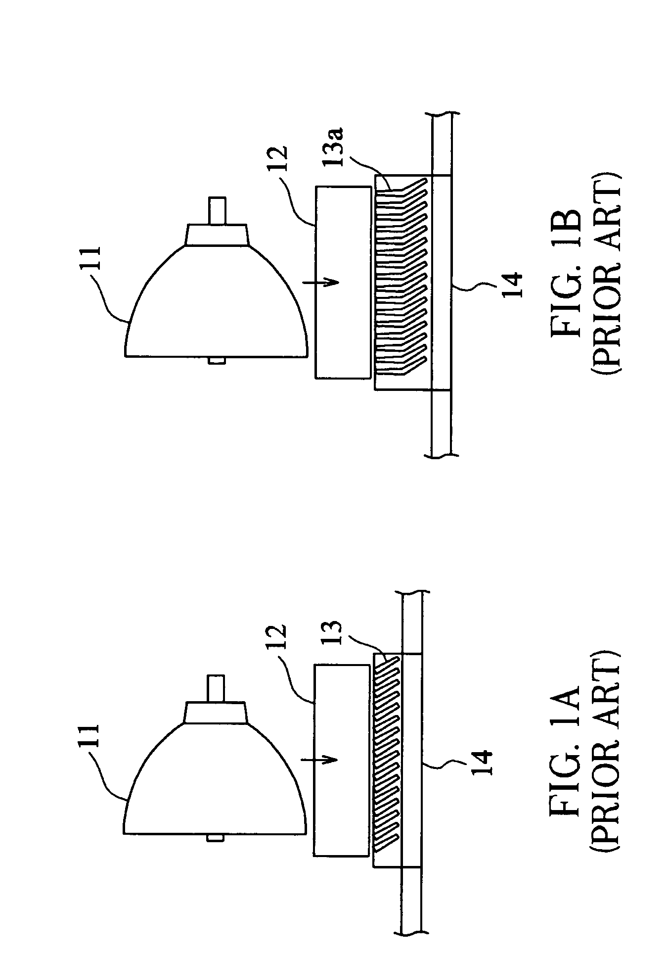
For the above reason, such a mask 13 or 13a of prior art has the following disadvantages: the air flow impedance during heat-dissipation process being large, vent temperature being high, fan efficiency being low, and noises existing during cooling process.

Method used


Image

  • Projector and light-shielding heat-dissipating mask for the same
  • Projector and light-shielding heat-dissipating mask for the same
  • Projector and light-shielding heat-dissipating mask for the same

Examples


Embodiment Construction

[0030] Embodiments of the present invention will be described in detail by referring to FIG. 2A to FIG. 6B in the following.

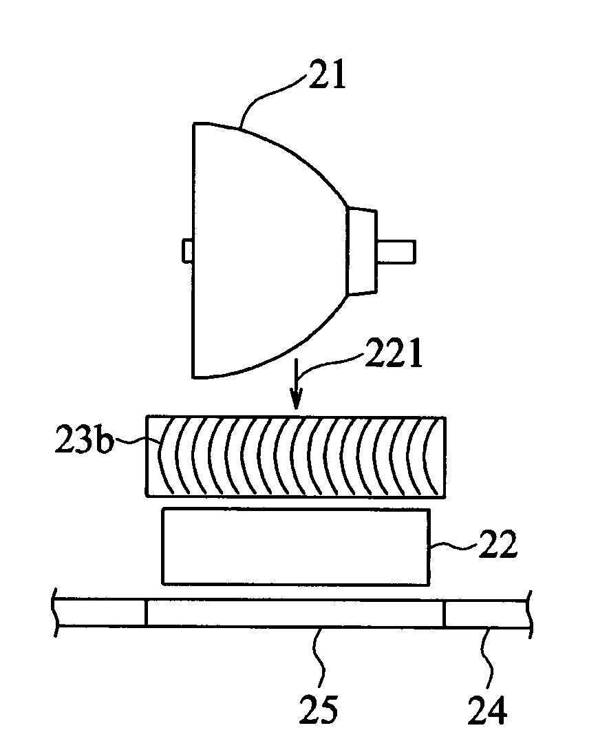
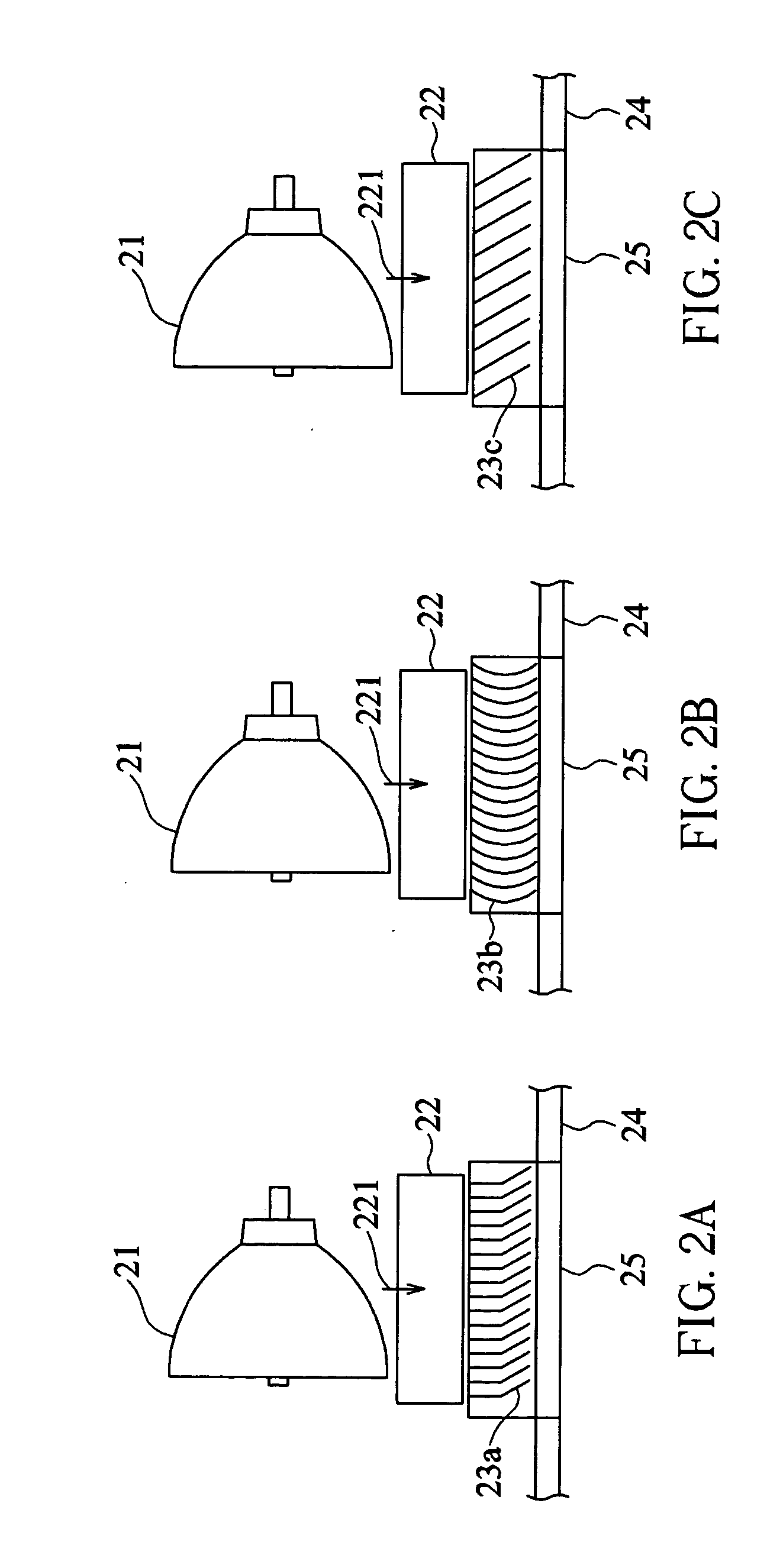
[0031] Referring now to FIG. 2A, in a first embodiment, the light-shielding heat-dissipating mask 23a for a projector according to the present invention, comprising a plurality of metal sheets (aluminum sheets in this embodiment) which have a V-shaped profile and are positioned in the same direction with a fixed gap between adjacent sheets, is positioned immediately adjacent to the fan 22 below the light source 21 of the projector, wherein the air-inlet side of the fan 22 faces the light source 21 for dissipating the heat generated by the light source 21.

[0032] In the first embodiment, the heat generated by the light source 21 is exhausted out of the air vent 25 of the casing 24 of the projector in the arrow direction 221 as the fan 22 is operating. The heat is directed to dissipate rapidly from the air vent 25 through the gap between adjacent sheets of the l...


PUM


Abstract

The present invention discloses a light-shielding heat-dissipating mask for a projector. The projector has a light source, a fan, and an air vent. The light-shielding heat-dissipating mask comprises a plurality of metal sheets which are positioned at the air vent for dissipating the heat generated by the light source and decreasing the possibility of the light emitted form the light source escaping out of the air vent.

Description

BACKGROUND OF THE INVENTION [0001] (a) Field of the Invention [0002] The present invention relates to a projector, and more particularly, to a light-shielding mask for a projector. [0003] (b) Description of Related Art [0004] Electronic signal image projectors, which have been developed extensively since 1990, have the characteristics of being easy to carry and adjust compared with overhead projectors or slide projectors. An electronic signal image projector, similar to an overhead projectors or a slide projector, uses a highly illuminant light bulb as a light source to project an image onto a white screen or wall. The display devices used in the projectors of nowadays include cathode ray tubes (CRT), high temperature polysilicon transmissive LCD panels, and digital light processing (DLP) elements. [0005] In the design of an electronic signal image projector, it is important to find the solution of the heat-dissipating problem of a light source. A fan is generally provided on the ri...

Claims


Application Information

Patent Timeline
IPC IPC(8): G03B21/16
CPCG03B21/16
Inventor CHANG, KUO-CHINGCHANG, HSIU-MINGLIN, CHIA-JUI
Owner DELTA ELECTRONICS INC
Learn More