Movement control apparatus, image scan apparatus and image scanning method

Inactive Publication Date: 2005-04-07
FUJIFILM CORP +1
View PDF5 Cites 9 Cited by
  • Summary
  • Abstract
  • Description
  • Claims
  • Application Information

AI Technical Summary

Benefits of technology

[0008] An object of the present invention is to provide a movement control device to control the movement of a controlled object like an area image sensor with high precision.
[0009] Another object of the present invention is to provide an image scan apparatus and an image scanning method to improve the quality and resolution of the scanned image by repeating to drive such movement control device to move the image sensor and scan the image on the object.
[0014] According to the present invention, since the movement of the movable stage is controlled such that the position information from the position detecting device becomes substantially the same as the target position, it is possible to move an object like an area image sensor with high precision. Moreover, controlling the movement of the object at the initial position can prevent the object from being deviated by hysteresis of a moving mechanism such as a piezo element.

Problems solved by technology

Even when the applied voltage to the piezo element is stable, however, the position of the area image sensor is continuously deviated by creeping and hysteresis that are original to the piezo element.
Such deviation in the position causes decrease in image quality of the scanned image.
Moreover, hysteresis of the piezo element changes the position of the area image sensor at the time when the applied voltage to the piezo element is zero.
In that case, the error in the position of the image sensor affects the quality of the scanned image.

Method used


Image

  • Movement control apparatus, image scan apparatus and image scanning method
  • Movement control apparatus, image scan apparatus and image scanning method
  • Movement control apparatus, image scan apparatus and image scanning method

Examples


Embodiment Construction

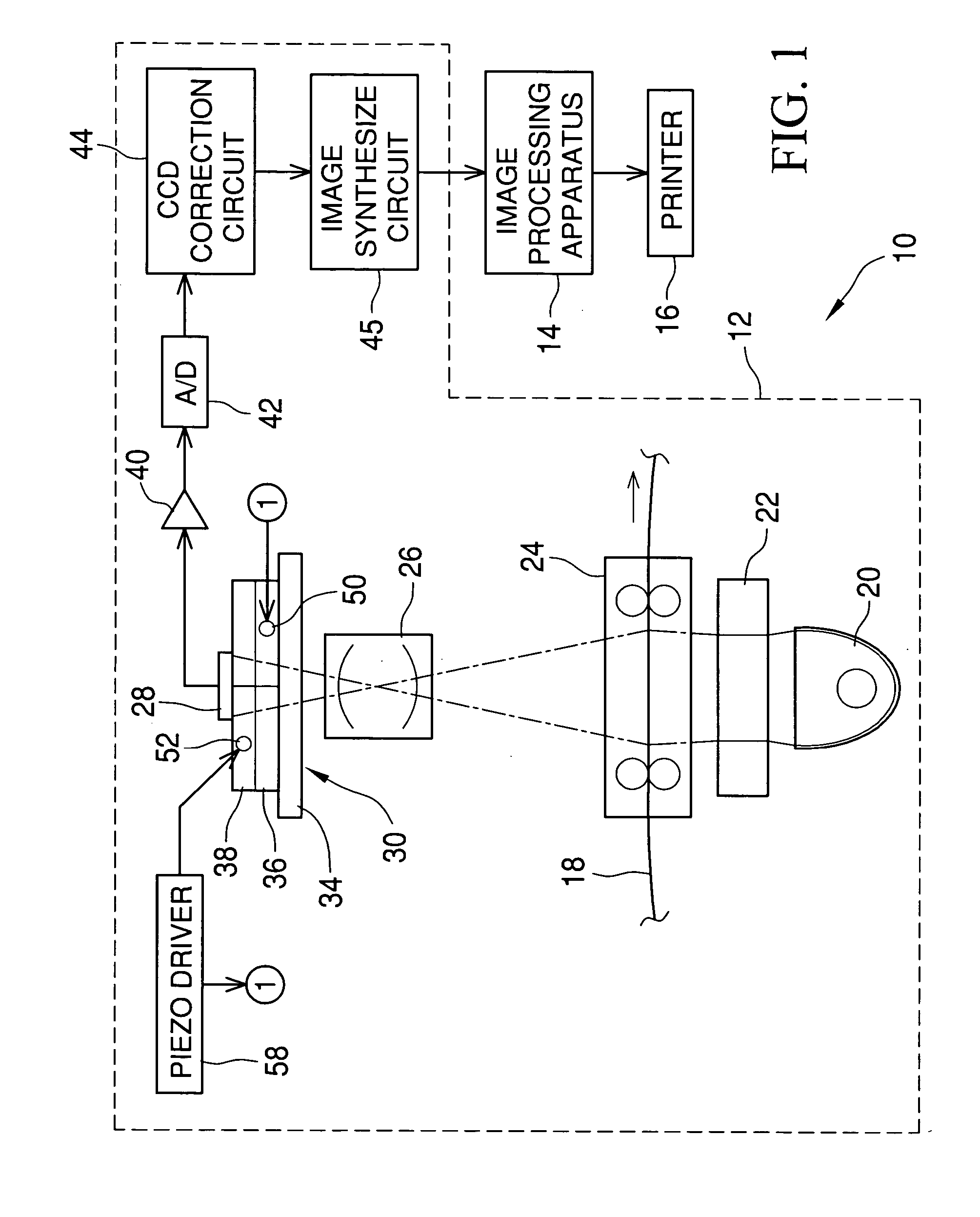
[0030] An embodiment according to the present invention is described with reference to the drawings. Referring to FIG. 1, a digital printer 10 comprises an image scan apparatus 12, an image processing apparatus 14 and a printer 16.

[0031] The image scan apparatus 12 scans an image on a photo film 18 photoelectrically to convert an optical film image into digital image data while feeding the photo film 18 frame by frame. The image scan apparatus comprises a light source 20, a diffusion box 22, a film carrier 24, a focusing lens 26, a CCD image sensor 28 and a CCD moving mechanism 30.

[0032] The light source 20 has LEDs or a lump to irradiate scan light of red, green and blue to the photo film 18. A lump driver and a filter control the amount of the scan light from the light source 20. The light source 20 may irradiate infrared light to detect a scratch or dust on the photo film 18. The scan light is diffused in the diffusion box 22 so that the scan light becomes uniform over the scan...


PUM


Abstract

A CCD image sensor is fixed on a Y-direction stage that is supported on an X-direction stage. When a piezo driver supplies voltage to an X-direction piezo element and a Y-direction piezo element, the CCD image sensor is moved in X and Y directions. The X-direction position sensor and the Y-direction position sensor detects the position information of the CCD image sensor in X and Y direction respectively, and send the position information to the piezo driver. The piezo driver sets a target movement of the CCD image sensor, and detects the actual movement of the CCD image sensor from the position information. The piezo driver adjusts the output voltage to the X-direction piezo element and the Y-direction piezo element such that the target movement becomes the same as the actual movement.

Description

BACKGROUND OF THE INVENTION [0001] 1. Field of the Invention [0002] The present invention relates to a movement control apparatus for controlling the movement of an object, and an image scan apparatus that has an imaging device to scan an image on a recording medium and the movement control apparatus to move the imaging device. [0003] 2. Description of the Related Art [0004] A well-known digital printer scans an image on a recording medium such as a photo film (a negative film and a reversal film, for example) photoelectrically to generate digital image data, and records the image by modulating an intensity of recording light and projecting the recording light on a photosensitive recording material. The digital printer has an advantage in improving the quality of the recorded image by image processing, such as color balance correction and sharpness correction, to the image data of scanned image. [0005] The image on the photo film is scanned by irradiating scan light from a light sou...

Claims


Application Information

Patent Timeline
IPC IPC(8): G03B27/46G06T1/00G06T3/00H04N1/028H04N1/04H04N1/387
CPCH04N1/047H04N1/19505H04N1/19515H04N1/19568H04N2201/0471H04N2201/04755H04N2201/04734H04N2201/04739H04N2201/02439H04N2201/04794
Inventor SAKAGUCHI, YASUNOBUERIKAWA, AKIHIKONISHIO, TOMONORI
Owner FUJIFILM CORP
Why Eureka
Try Eureka