Direct drive for a subscriber line differential ringing signal

a direct drive and subscriber line technology, applied in the field of subscriber line interface circuitry, can solve the problems of unbalanced and balanced ringing, unbalanced ringing, unbalanced ringing,

Inactive Publication Date: 2005-04-07
SILICON LAB INC
View PDF2 Cites 11 Cited by
  • Summary
  • Abstract
  • Description
  • Claims
  • Application Information

AI Technical Summary

Benefits of technology

In view of limitations of known systems and methods, a method of generating a subscriber line ringing signal for a subscriber line having first and second lines includes the step of providing a time-varying supply level, W(t). W(t) is applied to the first line while maintaining the second line at a pre-determined supply level for a duration T / 2. W(t) is applied to the second line while maintaining the first line at the pre-determined supply level for the duration T / 2. A resulting ringing signal component of the first line is L1(t). A resulting ringing signal component of the second line is L2(t). The first and second lines form a differential ringing signal line pair providing a differential ringing signal ΔL(t)=L1(t)−L2(t) having a period T.

Problems solved by technology

Various approaches to ringing signal generation include unbalanced and balanced ringing.
Unbalanced ringing is accomplished by holding one of the tip and ring lines at a pre-determined voltage level (e.g., ground) while providing the other line with the ringing signal.
One disadvantage of unbalanced ringing is that the maximum DC operating voltage for the SLIC must be the greater of: i) any DC offset plus the peak ringing voltage, or ii) the peak-to-peak ringing voltage.
Such voltage levels tend to limit fabrication of a ringing signal generator to either high voltage integrated circuits or discrete components.
As a result, balanced ringing requires a significantly lower DC operating voltage than unbalanced ringing.
One disadvantage of traditional balanced ringing is that AC matched ringing signals with a relative phase shift of 180° must be generated.

Method used


Image

  • Direct drive for a subscriber line differential ringing signal
  • Direct drive for a subscriber line differential ringing signal
  • Direct drive for a subscriber line differential ringing signal

Examples


Embodiment Construction

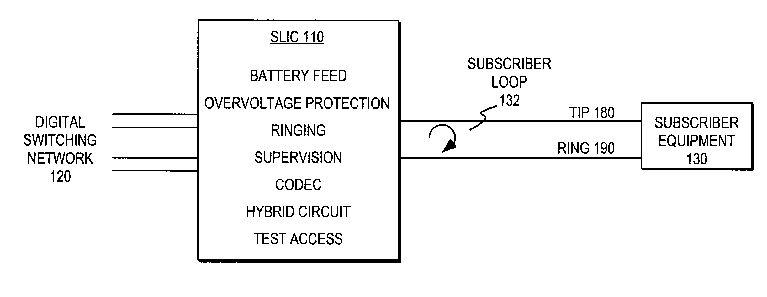
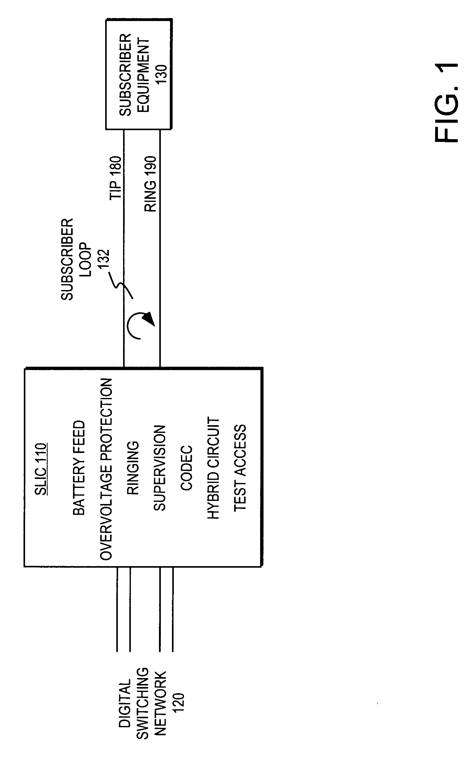
FIG. 1 illustrates functional elements of one embodiment of a subscriber line interface circuit (SLIC) 110 typically associated with plain old telephone services (POTS) telephone lines. The subscriber line interface circuit (SLIC) provides an interface between the digital switching network 120 of a local telephone company central exchange and a subscriber loop 132 including subscriber equipment 130.

The subscriber loop 132 is typically used for communicating analog data signals (e.g., voiceband communications) as well as subscriber loop “handshaking” or control signals. The analog data signals are typically on the order of 1 volt peak-to-peak (i.e., “small signal”). The subscriber loop control signals typically consist of a 48 V DC offset and an AC signal of 40-140 Vrms (i.e., “large signal”). The subscriber loop state is often specified in terms of the tip 180 and ring 190 lines of the subscriber loop.

The SLIC is expected to perform a number of functions often collectively referr...


PUM


Abstract

A method of generating a subscriber line ringing signal includes the step of applying a time-varying waveform W(t) to the tip line while maintaining the ring line at a pre-determined supply level for a duration T / 2. The time-varying waveform is subsequently applied to the ring line while maintaining the tip line at the pre-determined supply level for the duration T / 2. A subscriber line interface circuit apparatus includes a power supply providing a time-varying supply level, W(t). A signal processor controls a linefeed driver to alternately couple W(t) to one of the tip and ring lines while coupling an alternate supply level to the other of the tip and ring lines for a duration T / 2. In various embodiments, the resulting differential ringing signal is trapezoidal or sinusoidal.

Description

FIELD OF THE INVENTION This invention relates to the field of telecommunications. In particular, this invention is drawn to subscriber line interface circuitry. BACKGROUND OF THE INVENTION Subscriber line interface circuits are typically found in the central office exchange of a telecommunications network. A subscriber line interface circuit (SLIC) provides a communications interface between the digital switching network of a central office and an analog subscriber line. The subscriber line comprises a tip line and a ring line. The analog subscriber line connects the SLIC to a subscriber station or subscriber equipment such as a telephone at a location remote from the central office exchange. In conjunction with the subscriber equipment, the tip and ring lines form a subscriber loop. The SLIC communicates both data and control signals with the subscriber equipment. Control signals tend to require significantly greater voltages and currents than data signals (i.e., voiceband data)...

Claims


Application Information

Patent Timeline
Patent Type & Authority Applications(United States)
IPC IPC(8): H04M19/02
CPCH04M19/02
Inventor GEORGE, SCOTT A.
Owner SILICON LAB INC
Why Eureka
Try Eureka