Method for aligning and mounting two components on a support member in a positionally accurate manner

Inactive Publication Date: 2005-04-07
DAIMLER AG
View PDF16 Cites 15 Cited by
  • Summary
  • Abstract
  • Description
  • Claims
  • Application Information

AI Technical Summary

Benefits of technology

[0009] In the attachment region, the guide part and follower part may be fixed in position with respect to the support member, in a nut rigidly connected to the support member, using a screw guided through a hollow space of the distance element. This may provide a simple and cost-effective fastening method.
[0010] Initially, the distance element may be inserted into the follower opening in such a manner, that a centering region of the distance element juts out beyond the surface facing the guide part. The follower part is then placed, along with the distance element, on the guide part in such a manner, that the guide opening is penetrated by the centering region. Thus, a pressure sleeve, which may be conventional in principle and may be inexpensive and suitable for large-scale production, may be used as a distance element. Furthermore, the follower part and guide part may be aligned relatively to each other very easily, when the follower part is put on or mounted together with the pressure sleeve.
[0013] The fastening device may include a bolt guided through a hollow space of the distance element and a nut rigidly connected to the support member. This may provide that the components forming the joining region may be detached again from each other, if necessary. A nut rigidly connected to the support member may provide that fewer free parts are present.
[0014] The guide opening and the follower opening may be approximately circular. In this manner, the distance element may be particularly easy to manufacture from a standpoint of production engineering.
[0015] The guide opening may include a bevel on the side facing the follower part. This bevel has a centering effect when the distance element is inserted. In the case of the assembly of the attachment region, it is possible, in this manner, to put the follower part, along with the distance element, on the guide part with a high degree of process reliability.
[0017] In an example embodiment of the present invention, the distance element may be pre-fixed in position in the follower part by a nut and / or spring and has a bevel on the side facing the support member. In this manner, the distance element may already be reliably fixed in position in the follower part prior to mounting and may also be centered more effectively in the guide part during mounting.

Problems solved by technology

During the assembly of car-body components in automobile manufacturing, the problem of having to mount several components relatively to each other so as to have a particular, uniform gap between the components, occurs often.
In this context, it is, above all, difficult to simultaneously align the components relatively to each other and with respect to the body prior to finally mounting them.
However, this method is relatively expensive.
Secondly, a special manipulation tool has to be used to align the other components with respect to the reference marking.
The method is too complicated for mounting just two components to a support member in a positionally accurate manner.
The method may be applicable to the mounting of these components, since special requirements regarding their positionally accurate installation may be made, which may render manual, positionally accurate alignment and mounting of the individual parts complicated.

Method used


Image

  • Method for aligning and mounting two components on a support member in a positionally accurate manner
  • Method for aligning and mounting two components on a support member in a positionally accurate manner
  • Method for aligning and mounting two components on a support member in a positionally accurate manner

Examples


Embodiment Construction

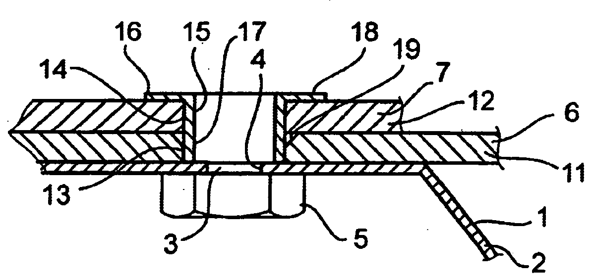
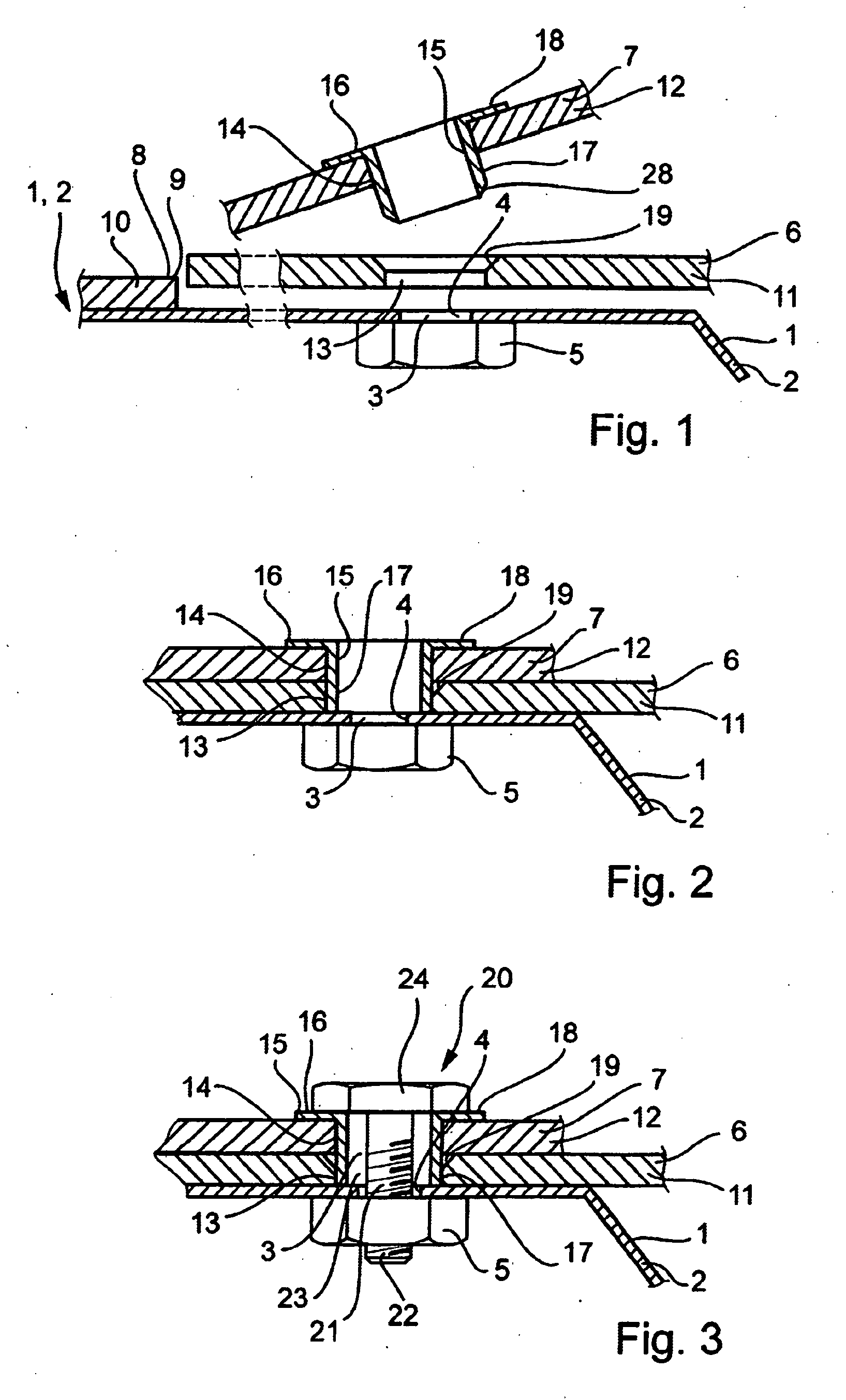
[0024] In FIG. 1, the components to be connected to each other in a positionally accurate manner are represented at the start of implementation of the method according to an example embodiment of the present invention. Illustrated is a support member 1, which may be, e.g., a car-body component 2 of a motor vehicle, to which components of a motor-vehicle front end are to be mounted. Located on support member 1 is an attachment region 3, which is formed, in this exemplary embodiment, by an opening 4 in support member 1 and a nut 5 rigidly connected to support member 1. In this attachment region 3, two other components, a guide part 6 and a follower part 7, shall be attached to support member 1. Support member 1 also has an alignment element 8, which may ensure that the components mounted to support member 1 are aligned. As illustrated in the drawing, this alignment element 8 may be formed, for example, by an edge 9 of an adjacent component 10, from which guide part 6 may assume a spec...


PUM


Abstract

In a method for aligning and mounting two components, a guide part and a follower part, on a support member in a positionally accurate manner, and a joining region of these components, in order to align two components relatively to each other and to other adjacent components, on a support member, in a positionally accurate manner and with a minimum amount of expenditure, the following method steps may be provided: the guide part is placed in position on the support member; a distance element is inserted into the openings in the guide part and the follower part so that it fixes the position of the follower part relative to the guide part; and the follower part and the guide part are jointly fixed in position in the attachment region, with respect to the support member.

Description

CROSS-REFERENCE TO RELATED APPLICATIONS [0001] The present application claims priority to Application No. 102 20 985.5, filed in the Federal Republic of Germany on May 11, 2002, which is expressly incorporated herein in its entirety by reference thereto. FIELD OF THE INVENTION [0002] The present invention relates to a method for aligning and mounting two components on a support member, as well as a joining region between two components and a support member. BACKGROUND INFORMATION [0003] During the assembly of car-body components in automobile manufacturing, the problem of having to mount several components relatively to each other so as to have a particular, uniform gap between the components, occurs often. In this context, it is, above all, difficult to simultaneously align the components relatively to each other and with respect to the body prior to finally mounting them. [0004] German Published Patent Application No. 199 12 181 describes a method for mounting components of a moto...

Claims


Application Information

Patent Timeline
IPC IPC(8): B60Q1/04B62D27/06B62D65/02B62D65/16F16B5/02
CPCB60Q1/0433B60Q1/045B62D27/065B62D65/16Y10T403/1624Y10T403/7123Y10T403/7111Y10T403/16F16B5/025
Inventor LUETZE, THOMASPELZ, ROMAN
Owner DAIMLER AG
Why Eureka
Try Eureka