Filter catalyst for purifying exhaust gases

a filter catalyst and exhaust gas technology, applied in physical/chemical process catalysts, metal/metal-oxide/metal-hydroxide catalysts, separation processes, etc., can solve the problems of increasing the temperature of burning deposited pms, increasing pressure loss, and advanced technology, etc., to suppress the increase of pressure loss resulting from the deposition of pms, and the oxidizing rate of pms is greatly increased.

Inactive Publication Date: 2005-04-07
TOYOTA JIDOSHA KK
View PDF2 Cites 55 Cited by
  • Summary
  • Abstract
  • Description
  • Claims
  • Application Information

AI Technical Summary

Benefits of technology

Thus, in accordance with the present exhaust gas-purifying filter catalyst, it is possible to upgrade the oxidizing ra

Problems solved by technology

However, regarding diesel engines, the regulations and the technological developments have been advanced less compared to those of gasoline engines because of the unique circumstances that the harmful components are emitted as particulates (i.e., particulate materials, such as carbonaceous fine particles, sulfuric fine particles like sulfates, and high-molecular-weight hydrocarbon fine particles, hereinafter c

Method used


Image

  • Filter catalyst for purifying exhaust gases
  • Filter catalyst for purifying exhaust gases
  • Filter catalyst for purifying exhaust gases

Examples


examples

The present filter catalyst will be hereinafter described in more detail with reference to specific embodiments and comparative examples.

example no.1

Example No. 1

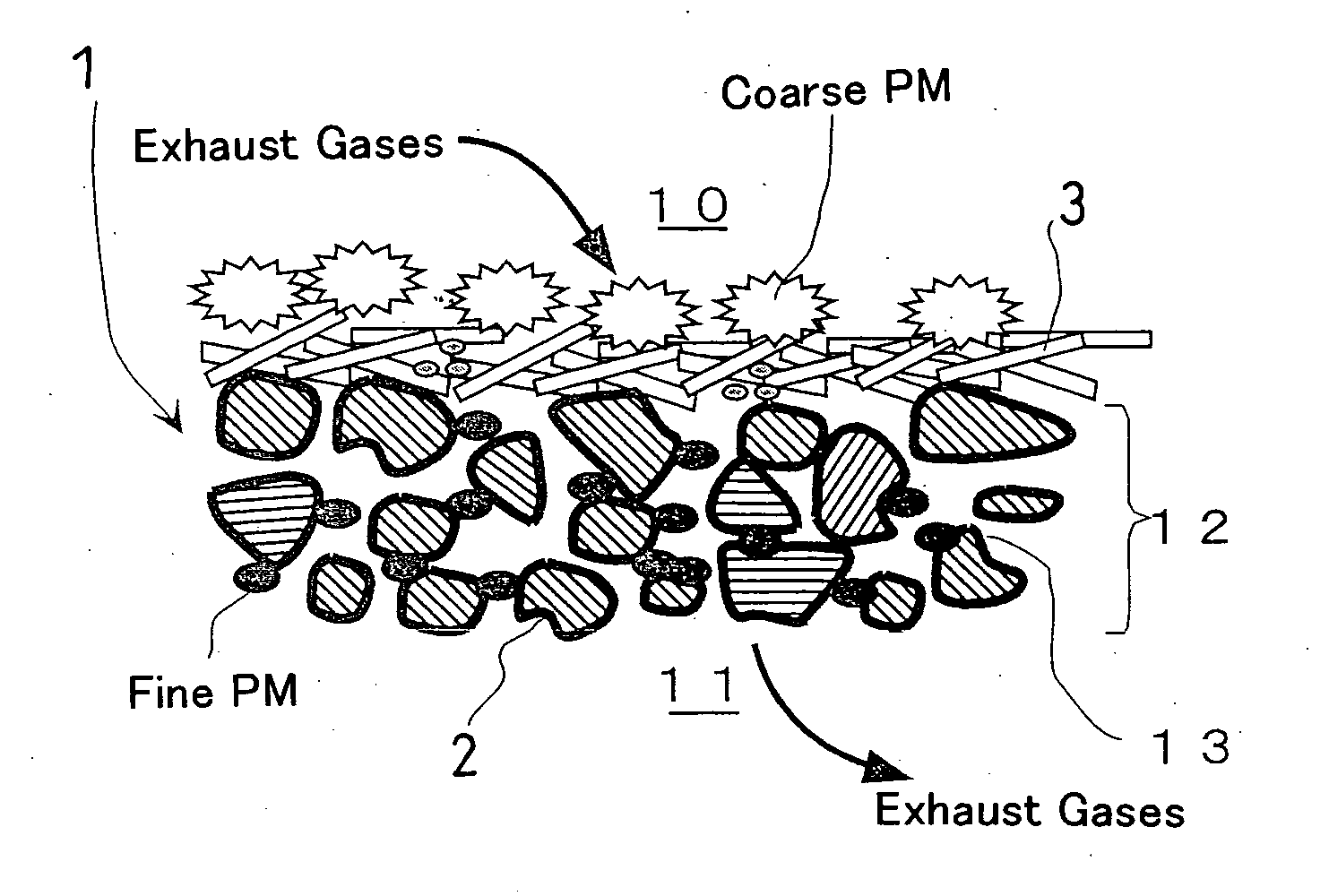
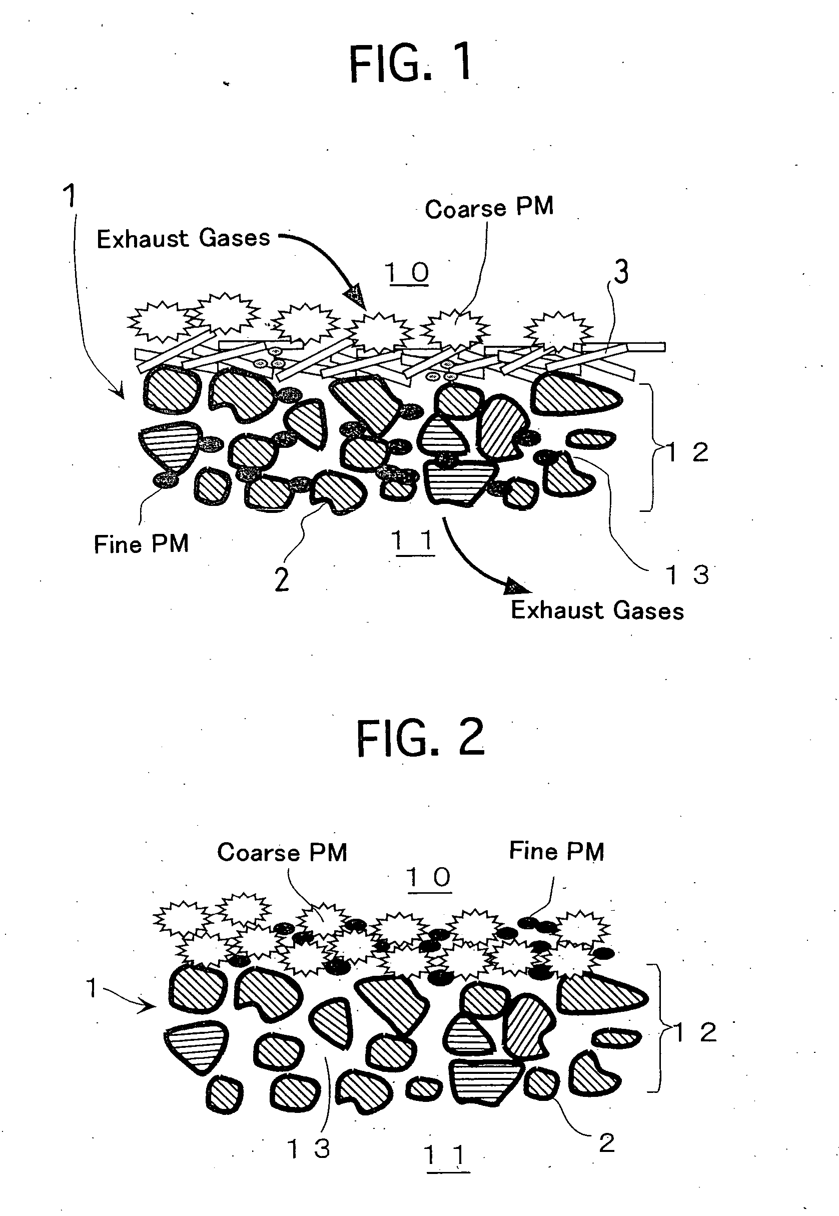
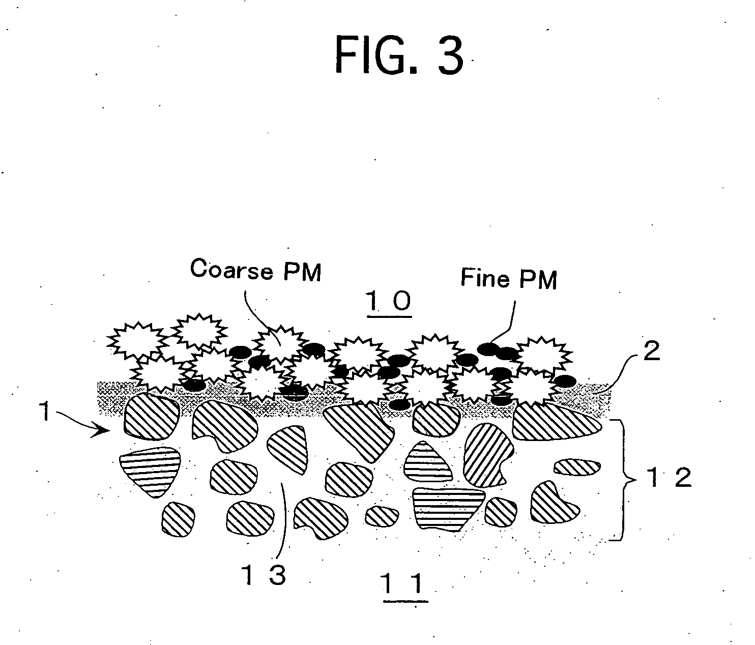
FIG. 1 illustrates a major cross-sectional view of a filter catalyst for purifying exhaust gases according to Example No. 1 of the present invention. The filter catalyst comprises a honeycomb filter 1, a catalytic layer 2, and a fibrous layer 3. The honeycomb filter 1 comprises inlet cells 10 clogged on the downstream side of the flow of exhaust gases, outlet cells 11 clogged on the upstream side of the flow of exhaust gases, and cellular walls 12 in which a great number of pores 13 are formed. Not only the pores 13 communicate with each other, but also communicate with the inlet cells 10 and the outlet cells 11.

The catalytic layer 2 comprises a support composed of a mixture powder of Al2O3 and CeO2, and Pt loaded on the support. Note that the catalytic layer 2 is formed on both surfaces of the cellular walls 12 and pores 13.

The fibrous layer 3 comprises entangled alumina fibers on which Pt is loaded, and is formed mainly on the surface of the cellular walls 12 of t...

example no.2

Example No. 2

A slurry was prepared which comprised an Al2O3 powder, a TiO2 powder, a ZrO2 powder, an alumina sol and ion-exchanged water, and was subjected to milling so that the solid particles had an average particle diameter of 1 μm or less. Except the thus prepared slurry was used, a coating layer was formed and a catalytic layer 2 was formed by loading Pt on the resulting coating layer in the same manner as Example No. 1.

The resultant honeycomb filter 1 provided with the catalytic layer 2 was measured for the water absorption. The honeycomb filter 1 was absorbed with a predetermined amount of a potassium acetate aqueous solution having a prescribed concentration. After the honeycomb filter 1 was dried, it was calcined to load K on the catalytic layer 2. Note that K was loaded in an amount of 0.2 mol with respect to 1 L of the honeycomb filter 1.

Finally, a fibrous layer 3 was formed in the same manner as Example No. 1. Note that the fibrous layer 3 was formed in an amount o...


PUM

PropertyMeasurementUnit
Massaaaaaaaaaa
Volumeaaaaaaaaaa
Percent by volumeaaaaaaaaaa

Abstract

A filter catalyst is for purifying exhaust gases, and comprises a honeycomb structure, a catalytic layer and a fibrous layer. The honeycomb structure comprises inlet cells clogged on a downstream side of a flow of the exhaust gases, outlet cells neighboring the inlet cells, and clogged on an upstream side of the flow of the exhaust gases, and cellular walls demarcating the inlet cells and the outlet cells, and having pores. The catalytic layer is formed on a surface of the cellular walls and an inner surface of the pores, and includes a porous oxide and a catalytic ingredient loaded on the porous oxide. The fibrous layer is formed on the outermost surface of the cellular walls of the inlet cells at least, and includes entangled fibrous substances composed of a heat-resistant material. The filter catalyst inhibits the pressure loss from increasing and upgrades the oxidizing rate of PMs greatly.

Description

BACKGROUND OF THE INVENTION 1. Field of the Invention The present invention relates to a filter catalyst for purifying exhaust gases, such as those emitted from diesel engines and including particulates. 2. Description of the Related Art Regarding gasoline engines, harmful components in the exhaust gases have been reduced securely by the strict regulations on the exhaust gases and the technological developments capable of coping with the strict regulations. However, regarding diesel engines, the regulations and the technological developments have been advanced less compared to those of gasoline engines because of the unique circumstances that the harmful components are emitted as particulates (i.e., particulate materials, such as carbonaceous fine particles, sulfuric fine particles like sulfates, and high-molecular-weight hydrocarbon fine particles, hereinafter collectively referred to as “PMs”). As exhaust gas-purifying apparatuses having been developed so far for diesel engin...

Claims


Application Information

Patent Timeline
IPC IPC(8): F01N3/02B01D53/94B01J23/58B01J23/63B01J35/04F01N3/022F01N3/035F01N3/08F01N3/28
CPCB01D53/944B01D53/9454F01N3/0222F01N3/035Y02T10/22F01N3/0842F01N3/2828F01N2330/06F01N2330/10F01N3/0821Y02T10/12C10L5/48C10L2290/08C10L2290/28C10L2290/30C10L2290/54Y02E50/30
Inventor OGURA, YOSHITSUGU
Owner TOYOTA JIDOSHA KK
Why Eureka
Try Eureka