Variable intensity wide-angle illuminator

a wide-angle illuminator and variable intensity technology, applied in the field of surgical instruments, can solve the problems of sub-optimal light refraction, wide-angle illuminators for ophthalmic surgery, and matching the light refracting index of vitreous eye fluid

Inactive Publication Date: 2005-04-07
ALCON INC
View PDF6 Cites 55 Cited by
  • Summary
  • Abstract
  • Description
  • Claims
  • Application Information

AI Technical Summary

Benefits of technology

[0010] To enable some of the advantages of the embodiments of this invention, the optical fiber can be operably coupled to the handpiece to enable linear displacement of the optical fiber and the optical element within the cannula. The handpiece can include a means, such as a push/pull mechanism, for adjusting the linear displacement of the optical fiber and the optical element. Other adjusting means as known to those in the art can also be used. The distal end (end closest to the surgical field) of the optical element can be co-incident with an open aperture of the cann...

Problems solved by technology

One disadvantage exhibited by some prior art wide-angle illuminators for ophthalmic surgery is a matching of the light refracting index of the vitreous eye fluid to that of the light refracting surface of the lens of the illuminator that comes in contact with the vitreous eye fluid.
Contact of the vitreous eye fluid with the light refracting surface of the light spreading lens of such prior art systems results in sub-optimal light refraction due to index switching caused by the vitreous eye fluid.
Another disadvantage of currently available wide-angle illuminators is glare.
Glare is unwanted stray radiation that provides no useful...

Method used


Image

  • Variable intensity wide-angle illuminator
  • Variable intensity wide-angle illuminator
  • Variable intensity wide-angle illuminator

Examples


Embodiment Construction

[0017] Preferred embodiments of the present invention are illustrated in the FIGURES, like numerals being used to refer to like and corresponding parts of the various drawings.

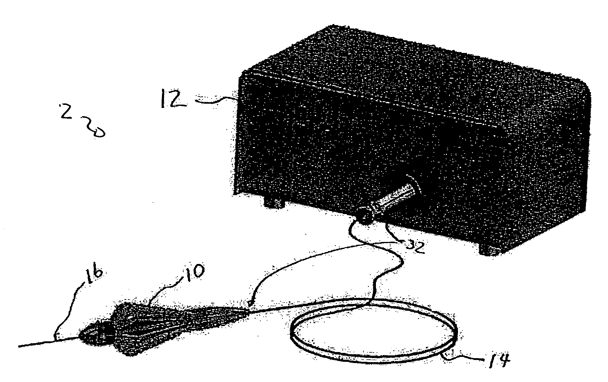
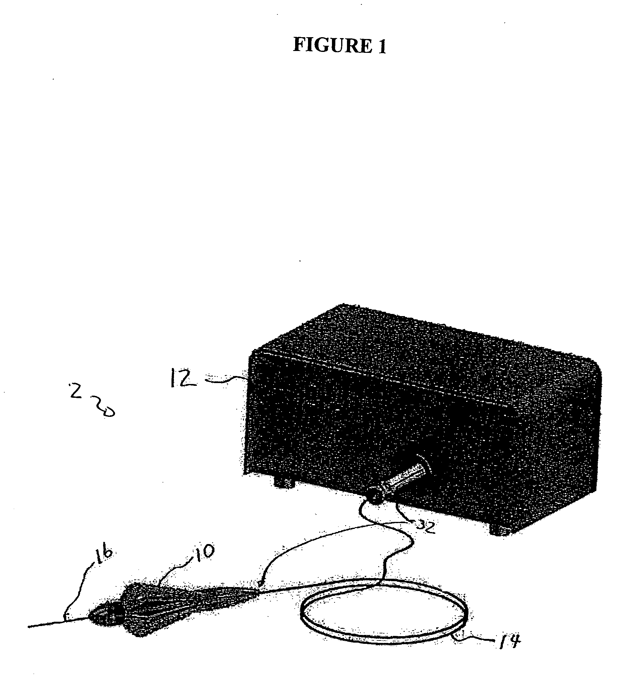
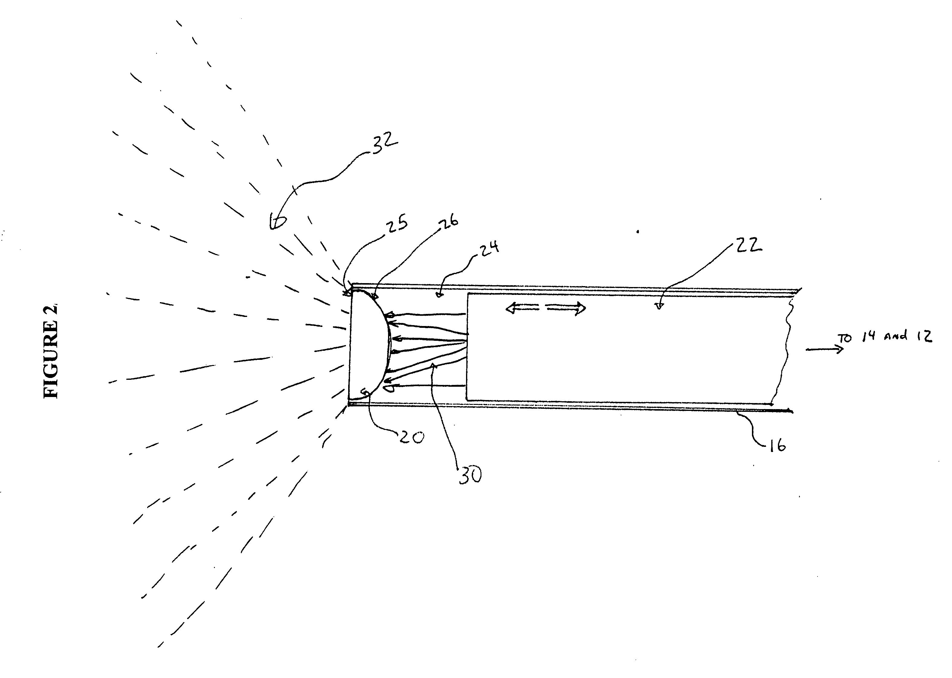
[0018] The various embodiments of the present invention provide for a small gauge (e.g., 19, 20, or 25 gauge) optical fiber based endo-illuminator device for use in surgical procedures, such as in vitreo-retinal / posterior segment surgery. Embodiments of this invention can comprise a handpiece, such as the Alcon-Grieshaber Revolution-DSP™ handpiece sold by Alcon Laboratories, Inc., Fort Worth, Tex., connected to a small gauge cannula (e.g., 19, 20, or 25 gauge). The inner dimension of the cannula can be used to house one, or a plurality of, optical fibers terminating in a diffusive optical element in accordance with the teachings of this invention. Embodiments of the wide-angle illuminator can be configured for use in the general field of ophthalmic surgery. However, it is contemplated and it will be realized ...


PUM


Abstract

A variable-intensity, wide-angle illuminator is disclosed, one embodiment comprising: a light source for providing a light beam; an optical cable, optically coupled to the light source for receiving and transmitting the light beam; a handpiece, operably coupled to the optical cable to receive the light beam; an optical fiber, operably coupled to the handpiece, wherein the optical fiber is optically coupled to the optical cable to receive and transmit the light beam; an optical element, optically coupled to a distal end of the optical fiber, for receiving the light beam and scattering the light beam to illuminate a surgical field, wherein the optical element comprises: a polymer matrix; and a plurality of microbubbles displaced within the polymer matrix; and a cannula, operably coupled to the handpiece, for housing and directing the optical fiber and the optical element. The optical element can be a small-gauge, diffusive optical element having circular or semi-ellipsoidal incident surfaces. For example, the optical element can be a 19, 20 or 25 gauge optical element. Further, the optical element, the cannula and the handpiece can be fabricated from biocompatible materials. The optical cable can comprise a first optical connector operably coupled to the light source and a second optical connector operably coupled to the handpiece (to optically couple the optical cable to the optical fiber housed within the handpiece and cannula).

Description

TECHNICAL FIELD OF THE INVENTION [0001] This application claims priority from U.S. Ser. No. 60 / 508,153 filed Oct. 2, 2003. [0002] The present invention relates generally to surgical instrumentation. In particular, the present invention relates to surgical instruments for illuminating an area during eye surgery. Even more particularly, the present invention relates to a variable intensity, small gauge, wide-angle illuminator for illumination of a surgical field. BACKGROUND OF THE INVENTION [0003] In ophthalmic surgery, and in particular in vitreo-retinal surgery, it is desirable to use a wide-angle surgical microscope system to view as large a portion of the retina as possible. Wide-angle objective lenses for such microscopic systems exist, but they require a wider illumination field than that provided by the cone of illumination of a typical fiber-optic probe. As a result, various technologies have been developed to increase the beam spreading of the relatively incoherent light prov...

Claims


Application Information

Patent Timeline
IPC IPC(8): A61B19/00A61F9/00
CPCA61B19/52A61F9/00A61B2019/5206A61B90/36A61B2090/306
Inventor CAZZINI, KARLBOOTH, DAVID E.
Owner ALCON INC
Why Eureka
Try Eureka