Voltage threshold ablation apparatus

a voltage threshold and ablation apparatus technology, applied in the field of electrosurgical procedures, can solve the problems of uncontrollable depth of ablation, final destruction of tissue, undesirable collateral damage to critical tissues and/or organs,

Inactive Publication Date: 2005-04-07
DFINE INC
View PDF14 Cites 94 Cited by
  • Summary
  • Abstract
  • Description
  • Claims
  • Application Information

AI Technical Summary

Problems solved by technology

Some RF ablation procedures rely on application of high currents and low voltages to the body tissue, resulting in resistive heating of the tissue which ultimately destroys the tissue.
These techniques suffer from the drawback that the heat generated at the tissue can penetrate deeply, making the depth of ablation difficult to predict and control.
This procedure is thus disadvantageous in applications in which only a fine layer of tissue is to be ablated, or in areas of the body such as the heart or near the spinal cord where resistive heating can result in undesirable collateral damage to critical tissues and / or organs.

Method used


Image

  • Voltage threshold ablation apparatus
  • Voltage threshold ablation apparatus
  • Voltage threshold ablation apparatus

Examples


first embodiment

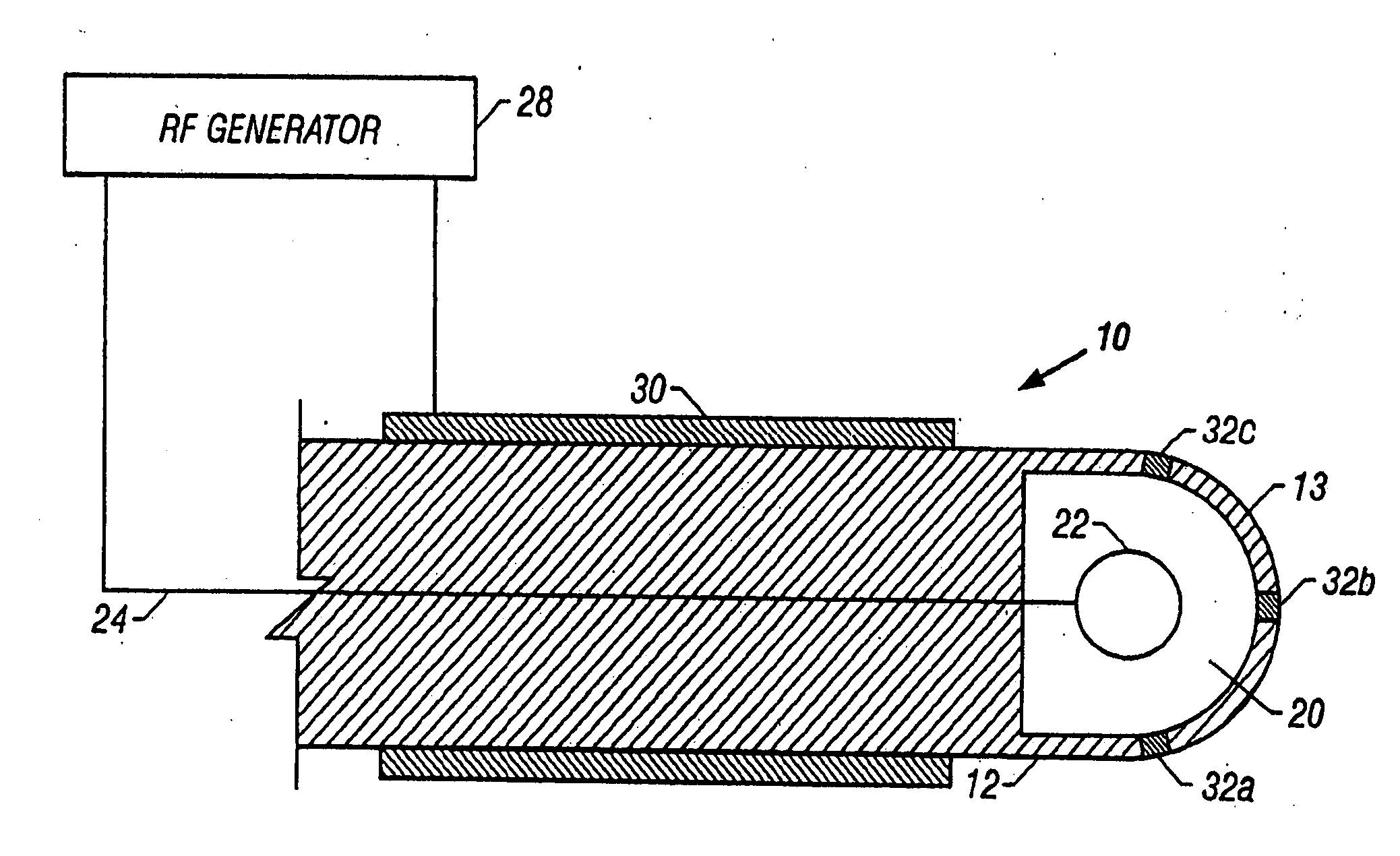
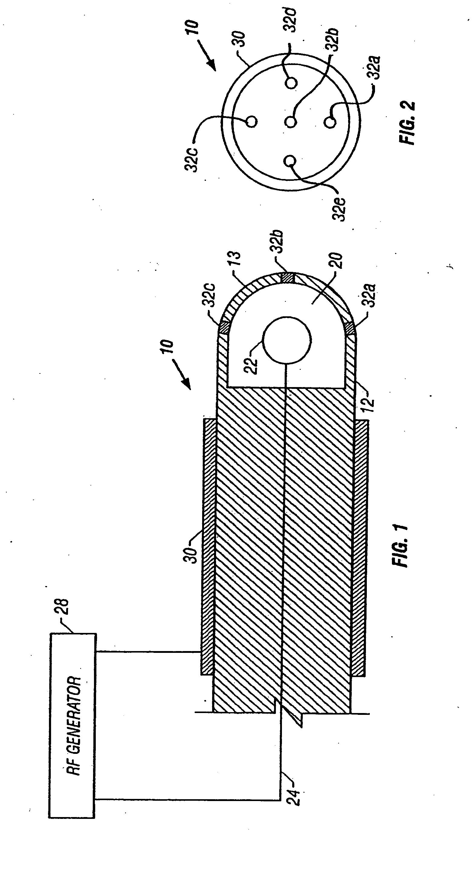
[0039] an ablation device 10 utilizing principles of the present invention is shown in FIGS. 1-2. Device 10 includes a housing 12 formed of an insulating material such as glass, ceramic, siliciumoxid, PTFE or other material having a high melting temperature. At the distal end 13 of the housing 12 is a sealed reservoir 20. An internal electrode 22 is disposed within the sealed reservoir 20. Electrode 22 is electrically coupled to a conductor 24 that extends through the housing body. Conductor 24 is coupled to an RF generator 28 which may be a conventional RF generator used for medical ablation, such as the Model Force 2 RF Generator manufactured by Valley Lab. A return electrode 30 is disposed on the exterior surface of the housing 12 and is also electrically coupled to RF generator 28.

[0040] A plurality of ablation electrodes 32a-c are located on the distal end of the housing 12. Ablation electrodes 32a-c may be formed of tungsten or any conductive material which performs well when ...

second embodiment

[0060] Operation of the embodiment of FIGS. 6A-6B is similar to that described with respect to FIGS. 5A-5B, and so most of that description will not be repeated. Operation differs in that use of the second embodiment includes the preliminary step of moving rod 126 proximally or distally to place plunger wall 123 and electrode 122 into positions that will yield a desired voltage threshold for the argon gas. Moving the plunger in a distal direction (towards the electrodes 132a-c) will decrease the volume of the reservoir and accordingly will increase the pressure of the argon within the reservoir and vice versa. Increases in argon pressure result in increased voltage threshold, while decreases in argon pressure result in decreased voltage threshold.

[0061] Moving the plunger 126 will also increase or decrease the distance d between electrode 122 and electrodes 132a-c. Increases in the distance d increase the voltage threshold and vice versa.

[0062] The rod 126 preferably is marked with...

third embodiment

[0065]FIGS. 7A and 7B show an alternative embodiment of an ablation device 210 that is similar to the device of FIGS. 6A and 6B. In this embodiment, argon is sealed within reservoir 220 by a wall 217. Rather than utilizing a plunger (such as plunger 121 in FIG. 6A) to change the volume of reservoir 220, the FIG. 7A-7B embodiment utilizes bellows 221 formed into the sidewalls of housing 212 and a pullwire 226 (which may double as the insulation for conductor 224) extending through internal electrode 222 and anchored to the distal end of the housing 212. Pulling the pullwire 226 collapses the bellows into a contracted position as shown in FIG. 7A and increases the pressure of the argon within the reservoir 220. Advancing the pullwire 226 expands the bellows as shown in FIG. 7B, thereby decreasing the pressure of the argon. The pullwire and bellows may be used to pre-select the threshold voltage, since (for a given temperature) increasing the argon pressure increases the threshold volt...


PUM


Abstract

A method and apparatus for treating tissue using an electrosurgical system. The system includes an electrosurgical system having an RF generator, a treatment electrode electrically coupled to the RF generator and positioned in contact with target tissue to be treated, and a spark gap switch positioned between the RF generator and the target tissue. The spark gap includes a threshold voltage and is configured to prevent conduction of current from the RF generator to the tissue until the voltage across the spark gap reaches the threshold voltage. The method includes the steps of using the RF generator to apply a voltage across the spark gap switch, the spark gap switch causing conduction of current from the RF generator to the target tissue once the voltage across the spark gap reaches the threshold voltage.

Description

CROSS-REFERENCES TO RELATED APPLICATIONS [0001] The present application is a continuation of U.S. patent application Ser. No. 10 / 135,135 (Attorney Docket No. 022356-000210), filed Apr. 30, 2002, which was a continuation of U.S. patent application Ser. No. 09 / 631,040, filed on Aug. 1, 2000, the full disclosures of which are incorporated herein by reference.FIELD OF THE INVENTION [0002] The present invention relates to the field of electrosurgery, and more particularly to methods for ablating, cauterizing and / or coagulating body tissue using radio frequency energy. BACKGROUND OF THE INVENTION [0003] Radio frequency ablation is a method by which body tissue is destroyed by passing radio frequency current into the tissue. Some RF ablation procedures rely on application of high currents and low voltages to the body tissue, resulting in resistive heating of the tissue which ultimately destroys the tissue. These techniques suffer from the drawback that the heat generated at the tissue can ...

Claims


Application Information

Patent Timeline
Patent Type & Authority Applications(United States)
IPC IPC(8): A61B18/14
CPCA61B18/14A61B2018/00666A61B2018/143A61B2018/1213A61B2018/00892
Inventor TRUCKAI, CSABASTRUL, BRUNO
Owner DFINE INC
Why Eureka
Try Eureka