
Air-fuel ratio control system and method for an internal combustion engine, and engine control unit

a technology of air-fuel ratio and control system, which is applied in the direction of electrical control, process and machine control, instruments, etc., can solve the problems of reducing the air-fuel ratio of a three-way catalyst, increasing the harmful substances in the exhaust gas emitted into the air, and taking a long time for the oxygen concentration of exhaust gas from all the cylinders to converge, so as to quickly and properly eliminate the variation in air-fuel ratio

Inactive Publication Date: 2005-04-07
HONDA MOTOR CO LTD
View PDF4 Cites 23 Cited by
  • Summary
  • Abstract
  • Description
  • Claims
  • Application Information

AI Technical Summary

Benefits of technology

[0007] It is an object of the present invention to provide an air-fuel ratio control system and method for an internal combustion engine, and an engine control unit, which are capable of quickly and properly eliminating variation in air-fuel ratio between a plurality of cylinders.

Problems solved by technology

In general, in an internal combustion engine, if the air-fuel ratio of a mixture supplied to a plurality of cylinders varies between the cylinders due to malfunction of an injector, an EGR system, or an evaporative fuel progressing system, the emission reduction rate of a three-way catalyst is degraded, which increases harmful substances in exhaust gases emitted into the air.
Therefore, when the difference is very large, it takes long time for the oxygen concentrations of exhaust gases from all the cylinders to converge to the target value.
As a result, it takes a longer time period to eliminate variation in air-fuel ratio between the cylinders, resulting in an increase in the amount of harmful substances emitted from the engine during the time period.

Method used


Image

  • Air-fuel ratio control system and method for an internal combustion engine, and engine control unit
  • Air-fuel ratio control system and method for an internal combustion engine, and engine control unit
  • Air-fuel ratio control system and method for an internal combustion engine, and engine control unit

Examples


first embodiment

[0249] The reason why the variation correction coefficient KEAFi is thus calculated based on the sum of the first and second filtered values KACT_Fc and KACT_Fr (step 90, 93 to 95) is as follows: As shown in FIG. 28, when the aforementioned simulative outputs KACTMI are input to the variation correction section 30 as the output KACT from the LAF sensor 14, with the third simulative output KACTMI3 alone being made smaller than the others, the first filtered value KACT_Fc changes with a relatively large amplitude, and the second filtered value KACT_Fr changes with a relatively small amplitude. In comparison with the first filtered value KACT_Fc indicated by a broken line in FIG. 28, the sum of the filtered values (KACT_Fc+KACT_Fr) becomes a negative value larger in its absolute value at the time of the third simulative output KACTMI3 being input, and becomes a smaller positive value at the time of the second simulative output KACTMI2 being input. As is apparent from this comparison, t...

second embodiment

[0258] As described above, the cylinder-by-cylinder variation correction coefficient KEAFi is calculated based on the sum of the first and second filtered values KACT_Fc and KACT_Fr, which exhibits a characteristic closer to actual variation in air-fuel ratio between the cylinders, such that the air-fuel ratios associated with the four cylinders #1 to #4 are leveled off, i.e. such that the sum of the first and second filtered values KACT_Fc and KACT_Fr becomes equal to 0. Therefore, variation in air-fuel ratio between the cylinders can be eliminated more quickly and properly.

[0259] It should be noted that when the absolute value |KACT-Fi (n)| of the calculating filtered value is smaller than the threshold value KACT_THRESH, the variation correction coefficient KEAFi may be fixedly held at its immediately preceding value, as in the variation of the first embodiment, without calculating the variation correction coefficient KEAFi.

[0260] Next, a third embodiment of the present inventi...


PUM


Abstract

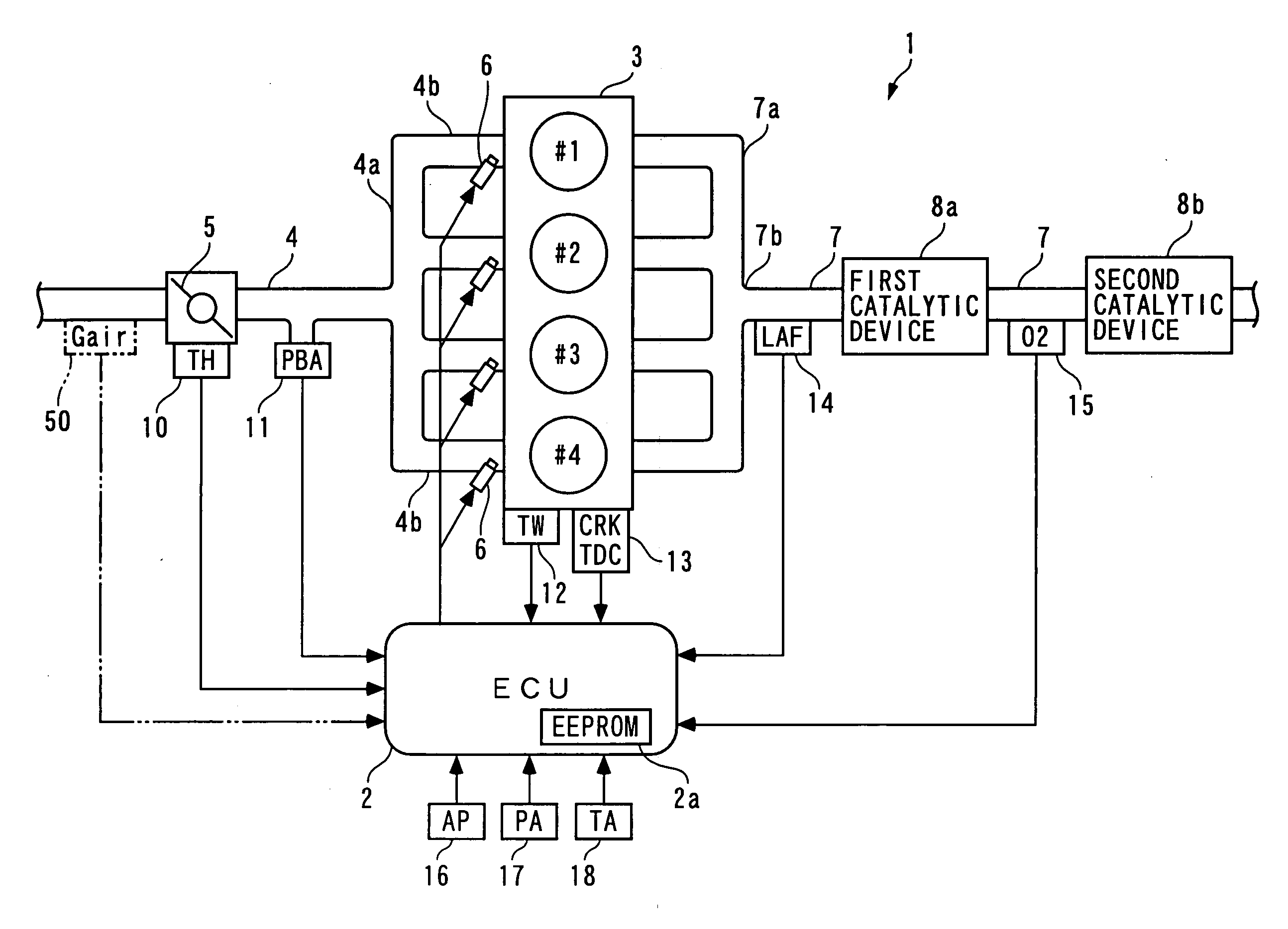
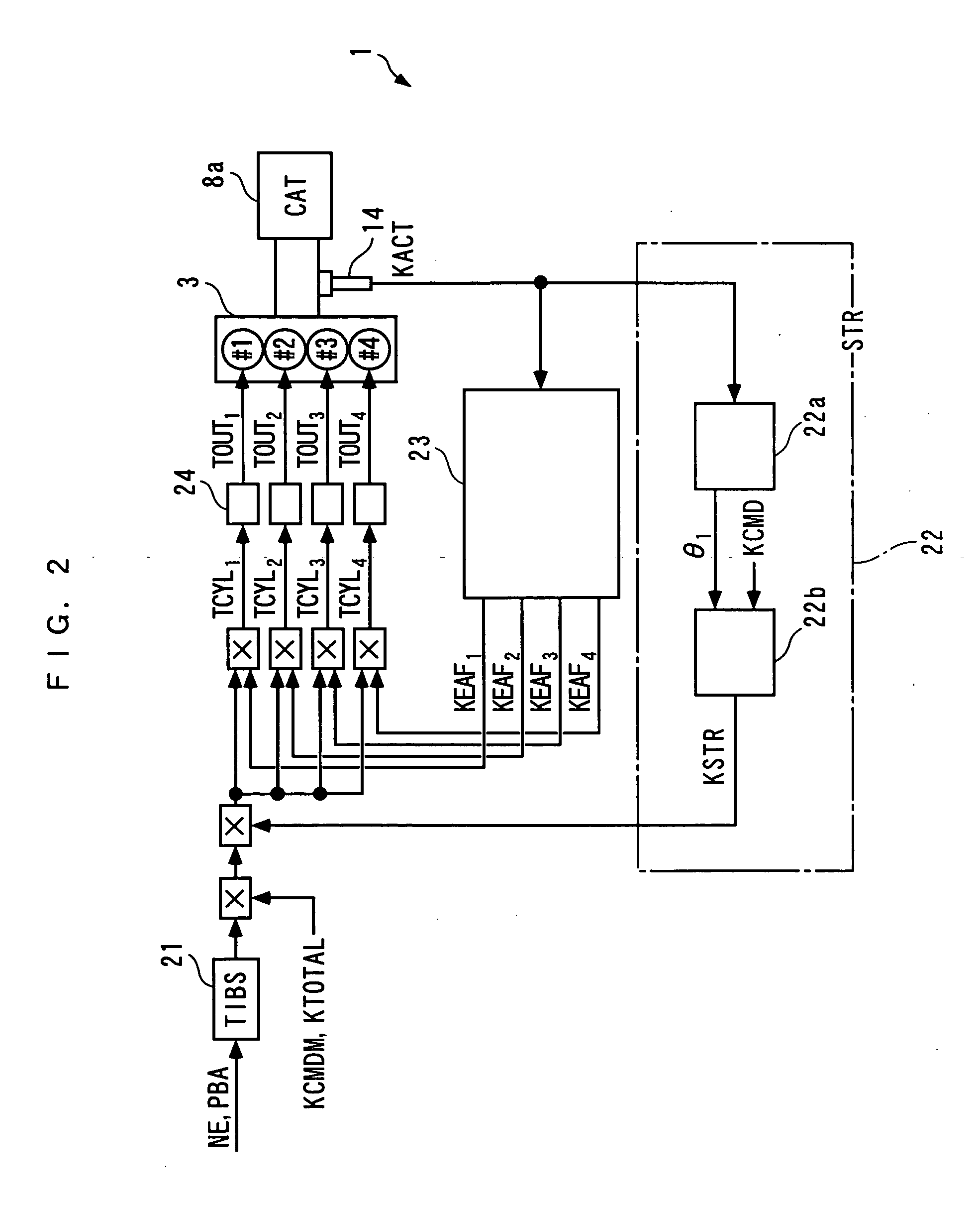
An air-fuel ratio control system for an internal combustion engine, which is capable of quickly and properly eliminating variation in air-fuel ratio between a plurality of cylinders. The air-fuel ratio control system 1 controls the amount of fuel to be supplied to first to fourth cylinders #1 to #4, on a cylinder-by-cylinder basis, thereby controlling the air-fuel ratio of a mixture supplied to each of the cylinders. A LAF sensor 14 delivers to an ECU 2 an output KACT indicative of the air-fuel ratio of exhaust gases emitted from the cylinders and merged. A cycle filter 23a and a rotation filter 23b filters the output KACT from the LAF sensor 14 such that components in respective bands of a first frequency fr1 and a second frequency fr2 are allowed to pass therethrough. A final fuel injection amount TOUTi is determined, on a cylinder-by-cylinder basis, according to a first filtered value KACT_Fc or a second filtered value KACT_Fr such that the amplitude of the filtered value KACT_Fc or KACT_Fr converges to a predetermined value.

Description

BACKGROUND OF THE INVENTION [0001] 1. Field of the Invention [0002] The present invention relates to an air-fuel ratio control system and method for an internal combustion engine, and an engine control unit, which control the amount of fuel to be supplied to a plurality of cylinders, on a cylinder-by-cylinder basis, to thereby control the air-fuel ratio of a mixture supplied to each of the cylinders. [0003] 2. Description of the Related Art [0004] In general, in an internal combustion engine, if the air-fuel ratio of a mixture supplied to a plurality of cylinders varies between the cylinders due to malfunction of an injector, an EGR system, or an evaporative fuel progressing system, the emission reduction rate of a three-way catalyst is degraded, which increases harmful substances in exhaust gases emitted into the air. To eliminate the inconvenience, there has conventionally been proposed an air-fuel ratio control system e.g. in Japanese Laid-Open Patent Publication (Kokai) No. 2002...

Claims


Application Information

Patent Timeline
IPC IPC(8): F02D45/00F02D41/00F02D41/14F02D41/34
CPCF02D41/008F02D41/1401F02D2041/1432F02D41/2454F02D2041/1431F02D41/1456
Inventor MIZUNO, TAKAHIDEYASUI, YUJIMAKI, HIDETAKA
Owner HONDA MOTOR CO LTD
Learn More