Hydraulic control device, system and method for controlling actuator device

a technology of hydraulic control device and actuator device, which is applied in the direction of electric control, fuel injection pump, machine/engine, etc., can solve the problems of inability to close the high pressure port, small supply energy, etc., and achieve the effect of improving the controllability of the fuel injection system and the injection ra

Inactive Publication Date: 2005-04-14
DENSO CORP
View PDF7 Cites 11 Cited by
  • Summary
  • Abstract
  • Description
  • Claims
  • Application Information

AI Technical Summary

Benefits of technology

The present invention is directed to overcome the foregoing problems. Accordingly, it is an object of the present invention to provide a hydraulic control device capable of controlling stably a valve member so as to keep it at a half-lift position, thereby improving the controllability of injection rate of fuel injection system, that of decompression control of a common-rail or the like.
It is another object of the present invention to provide a system and a method for an actuator device, which are capable of controlling simply energy delivered to an actuator so as to set it to suitable energy.
According to one aspect of the present invention, when supplying energy that the actuator requires to move the valve member so as to open the low pressure port, the actuator makes move (lift) the valve member toward the high pressure port. The supplied energy, however, is smaller than energy which the actuator requires to move the valve member so as to close the high pressure port so that it is impossible to close the high pressure port by the valve member. That is, setting the energy supplied to the actuator to suitable energy smaller than the energy required to close the high pressure port permits the valve member to be kept at a half lift position between the low pressure port and the high pressure port, making it possible to stably control a lift amount of the valve member being moved to the half lift position by an amount of energy supplied to the actuator or a voltage supplied thereto.
As a result, even if the individual differences of the actuator devices occur, it is possible to prevent the variations of the actuator devices, the loss of the energy and the variation of the injection characteristic over time due to wear.

Problems solved by technology

The supplied energy, however, is smaller than energy which the actuator requires to move the valve member so as to close the high pressure port so that it is impossible to close the high pressure port by the valve member.

Method used


Image

  • Hydraulic control device, system and method for controlling actuator device
  • Hydraulic control device, system and method for controlling actuator device
  • Hydraulic control device, system and method for controlling actuator device

Examples


first embodiment

(First Embodiment)

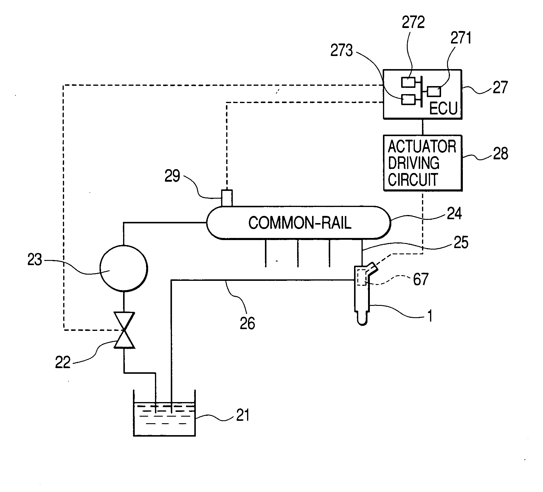
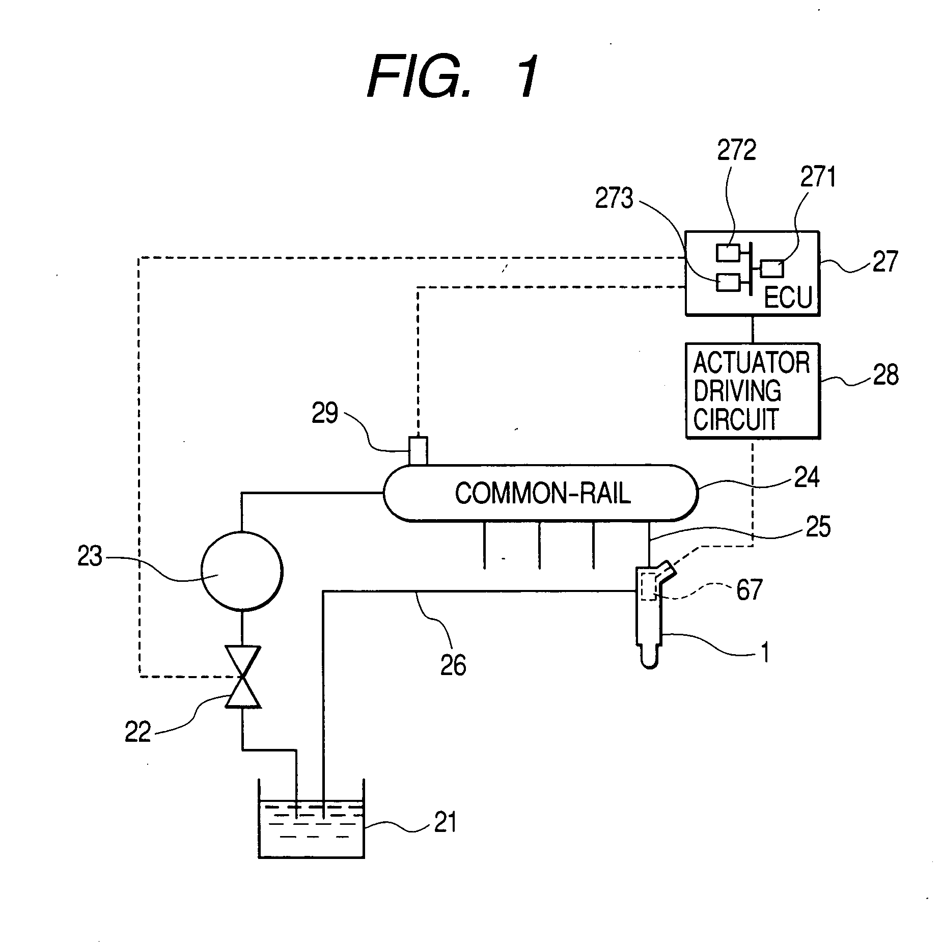
FIG. 1 shows a configuration of a common-rail fuel injection system to which a first embodiment of the present invention is applied.

The common-rail fuel injection system comprises injectors (fuel injection valves) 1 for respective cylinders of the common-rail fuel injection system. A number of injectors correspond to that of cylinders of the common-rail fuel injection system. Incidentally, in FIG. 1, one injector 1 is only shown.

The injector 1 is communicated through a delivery line 25 with a common-rail 24, which is common among the cylinders. The injector 1 is subjected to the fuel delivered from the common-rail 24 so as to inject fuel at an injection pressure into a combustion chamber of the corresponding cylinder, injection pressure which is substantially equal to a fuel pressure in the common-rail 24.

Fuel in a fuel tank 21 is delivered by the pressure of a high-pressure pump 23 to a common-rail 24 so as to be accumulated therein at a high pressure.

Fuel...


PUM


Abstract

A supplying unit supplies energy to an actuator so that the supplied energy is kept therein, making displacement the actuator. An interrupting unit interrupts the supply of energy to cause the actuator to discharge the kept energy, making displacement the actuator. A converting unit is adapted to convert the displacement of the actuator corresponding to the kept energy into hydraulic pressure applied to the valve member, moving the valve member to open the low pressure port and close the high pressure port. The convert unit converts the displacement of the actuator corresponding to the discharged energy into hydraulic pressure applied to the valve member, moving the valve member to open the high pressure port and close the low pressure port. Energy which the actuator requires to move the valve member so as to close the high pressure port is larger than energy which the actuator requires to move the valve member so as to open the low pressure port.

Description

BACKGROUND OF THE INVENTION 1. Field of the Invention The present invention relates to an actuator device, such as a hydraulic control device. in which an actuator is installed, a control system and a method for the actuator device. More particularly, the present invention relates to an actuator device, such as a hydraulic device, applied to, for example, an internal combustion engine, such as a diesel engine, a control system and a method for the actuator device. 2. Description of the Related Art Conventional actuators that energization can make operate include an actuator, such as a piezoelectric actuator, a magnetostrictive actuator, or the like, which deforms according to amount of energy based on the energization and kept by itself, thereby generating driving force, such as pressing force. Conventional actuator devices in each of which the above actuator is installed, such as, hydraulic control valves, fuel injectors and so on, are proposed. The actuator devices are appli...

Claims


Application Information

Patent Timeline
Patent Type & Authority Applications(United States)
IPC IPC(8): F02D41/00F02D41/24F02D41/34F02M47/02F02M47/04F02M61/16F02M63/00F02M63/02
CPCF02D41/008F02D41/2435F02D41/2467F02D2200/0602F02M47/027F02M2200/704F02M51/0603F02M61/167F02M63/0026F02M63/0225F02M2200/21F02M47/046F02M2200/8007
Inventor IGASHIRA, TOSHIHIKOHAYASHI, SATOSHI
Owner DENSO CORP
Why Eureka
Try Eureka