Ink jet head and ink jet printing apparatus having the head

a printing apparatus and ink jet technology, applied in the direction of printing, pretreatment surfaces, coatings, etc., can solve the problems of affecting the adhesion of the surface, and provoking higher manufacturing costs, etc., and achieve good adhesion

Inactive Publication Date: 2005-04-14
CANON KK
View PDF9 Cites 47 Cited by
  • Summary
  • Abstract
  • Description
  • Claims
  • Application Information

AI Technical Summary

Benefits of technology

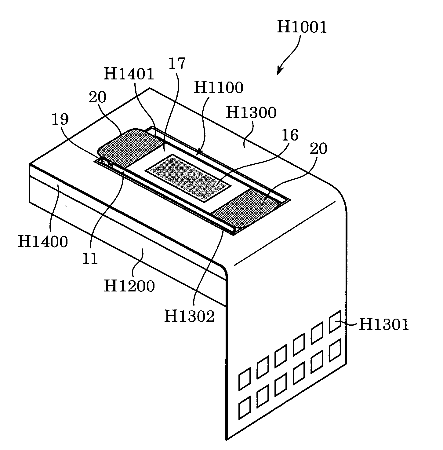
[0019] Another object of the present invention is to provide an ink jet head and an ink jet printing apparatus that show good adhesion at the boundary between a sealant for protecting a head substrate (chip-periphery sealant) and a sealant for sealing an electric splice (ILB sealant).

Problems solved by technology

However, these conventional techniques are susceptible to further improvement.
For example, if the ILB sealant is applied and cured after the chip-periphery sealant is applied and cured, it takes a long time to cure these two sealants, dedicated thermostats must be provided for curing the chip-periphery sealant and the ILB sealant, respectively, and spaces for the two thermostats are required, thus inviting higher cost of manufacture.
However, the following problems have arisen.
In some cases, a thin uncured layer is formed at the boundary between the chip-periphery sealant and the ILB sealant, and the ink penetrates the uncured layer to thereby cause electrical failures.

Method used


Image

  • Ink jet head and ink jet printing apparatus having the head
  • Ink jet head and ink jet printing apparatus having the head
  • Ink jet head and ink jet printing apparatus having the head

Examples


Embodiment Construction

[0031] The present invention has been achieved based on the following findings reached after intensive investigations to reveal the chemical mechanisms underlying the above-mentioned problems in the prior art.

[0032] (1) The bisphenol-A type epoxy resin begins to cure prior to the polybutadiene-modified epoxy resin and consumes the curing agent in the chip-periphery sealant at the boundary to thereby prevent the polybutadiene-modified epoxy resin from curing. Thus, an uncured layer is formed, into which ink penetrates to invite electrical failures.

[0033] (2) The solvent and hydrolysates such as lower alcohol and acid derived from the sealants are gasified to form cavities in the cured article, thus deteriorating the tight adhesion between the ILB sealant and the chip-periphery sealant.

[0034] (3) If the chip-periphery sealant and the ILB sealant comprise different base resins, they have different linear expansion coefficients, and thus gaps or space often forms at the boundary due ...


PUM


Abstract

An ink jet head has a head substrate including discharge elements for discharging ink, with an electric wiring board being electrically connected to the head substrate, in which the periphery of the head substrate is sealed with a first sealant, and an electric splice between the head substrate and the electric wiring board is sealed with a second sealant. The first and second sealants contain the same base resin and curing agent, and the second sealant shows higher hardness than the first sealant after curing. This ink jet head is free from problems such as cavities and fissures at the boundary of the two sealants caused by a difference in linear expansion coefficients.

Description

[0001] This application claims priority from Japanese Patent Applications Nos. 2003-350904 filed Oct. 9, 2003, and 2004-259628 filed Sep. 7, 2004, which are hereby incorporated by reference herein. BACKGROUND OF THE INVENTION [0002] 1. Field of the Invention [0003] The present invention relates to an ink jet head and an ink jet printing apparatus having the head. [0004] 2. Description of the Related Art [0005] According to a recording system using an ink jet head, heat energy or vibration energy is applied to ink to discharge the ink as fine droplets from nozzles to thereby form an image on a recording medium. An example of a method for manufacturing an ink jet head can be found in Japanese Patent Application Laid-open No. 2002-19120. [0006] According to such a manufacturing method, an ink jet head is manufactured in the following manner. Initially, heat elements (discharge element part) and a wiring conductor for supplying electric power to the heat elements are formed on a silicon...

Claims


Application Information

Patent Timeline
Patent Type & Authority Applications(United States)
IPC IPC(8): B41J2/14B41J2/16
CPCB41J2/14024B41J2/14072B41J2/1629B41J2/1623B41J2/1603
Inventor SHIMOMURA, MASAKOINAMOTO, TADAYOSHIISHIZUKA, KAZUNARIKUROBE, RYOICHIROSATO, YOHEISHIMOMURA, AKIHIKOIMAMURA, ISAO
Owner CANON KK
Why Eureka
Try Eureka