Optical signal equalizer with adjustable linear filter

a linear filter and optical signal technology, applied in the field of optical signal equalizer with adjustable linear filter, can solve the problems of data bits embedded in electronic signals being erroneously interpreted, the signal is dispersed, and the interpretation of data bits is difficult to understand, so as to achieve the effect of reducing the effect of dispersion

Inactive Publication Date: 2005-04-14
II VI DELAWARE INC
View PDF7 Cites 5 Cited by
  • Summary
  • Abstract
  • Description
  • Claims
  • Application Information

AI Technical Summary

Benefits of technology

One embodiment of the invention includes a method of mitigating the effects of dispersion in a high frequency communication channel. The method receives a signal. The signal is passed through an adjustable linear filter. The adjustable linear filter has a number of coefficients...

Problems solved by technology

Further, for portions of the signal that are reflected back and forth, each portion may take a different path resulting in different velocities at which the portions of the signal travel through the fiber-optic cable.
Thus, a single signal may take several paths resulting in dispersion of the signal as it travels along the fiber-optic cable.
The more closed an eye is, the more difficult it is to interpret data bits.
Because of the dispersion, some of the data bits embedded in the electronic signals may be erroneously interpreted.
While dispersio...

Method used


Image

  • Optical signal equalizer with adjustable linear filter
  • Optical signal equalizer with adjustable linear filter
  • Optical signal equalizer with adjustable linear filter

Examples


Embodiment Construction

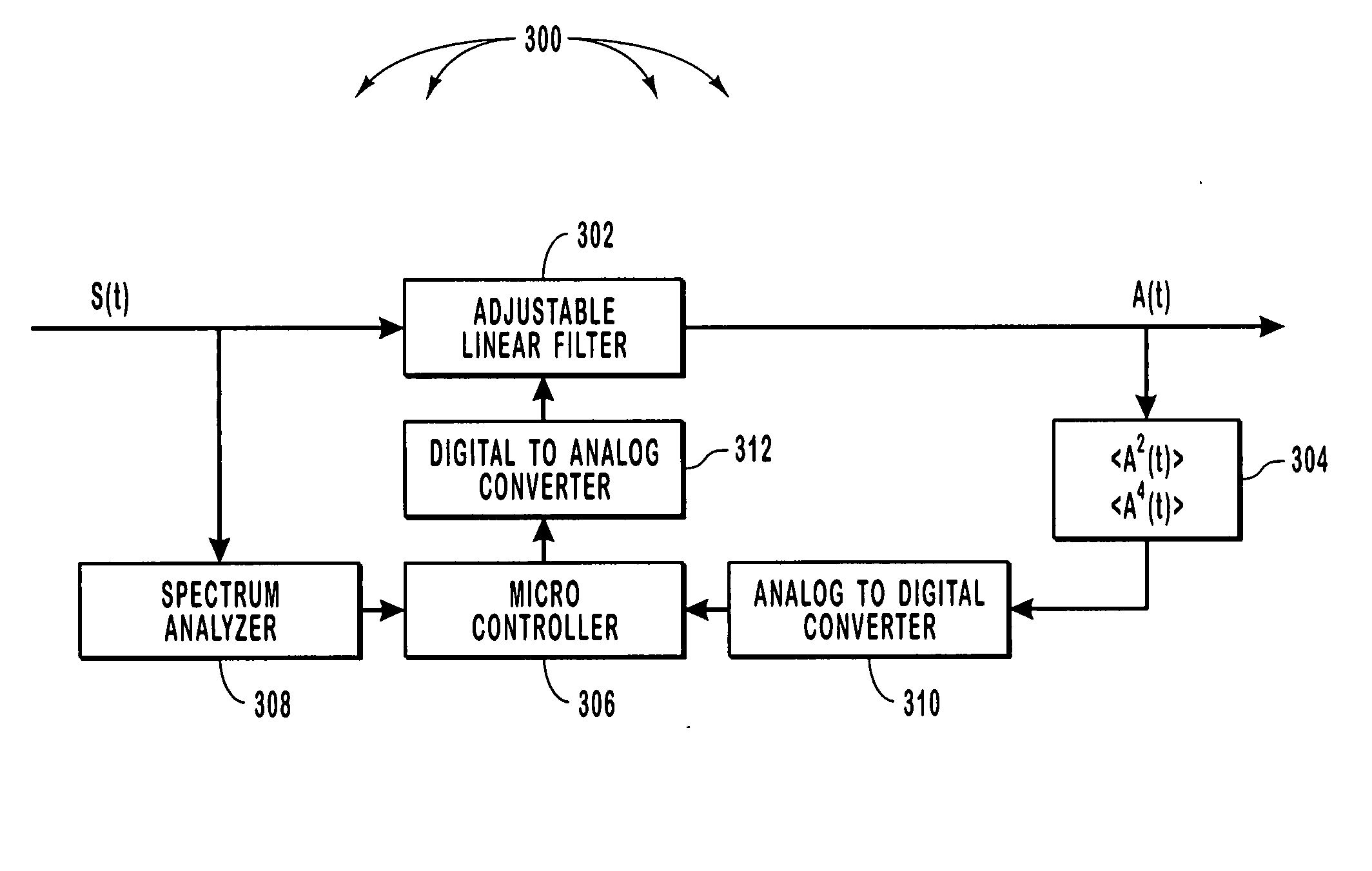
Embodiments of the invention compensate for dispersion related effects caused by a communications channel. Embodiments pass a signal that has traveled on the channel through a linear filter. The linear filter is designed to counteract the dispersion related effects. These embodiments calculate a figure of merit for a signal that is output from the linear filter. The figure of merit may be a function of the second and fourth moments of the output. Based on the value of the figure of merit, coefficients of the linear filter can be adjusted so as to improve the performance of the linear filter.

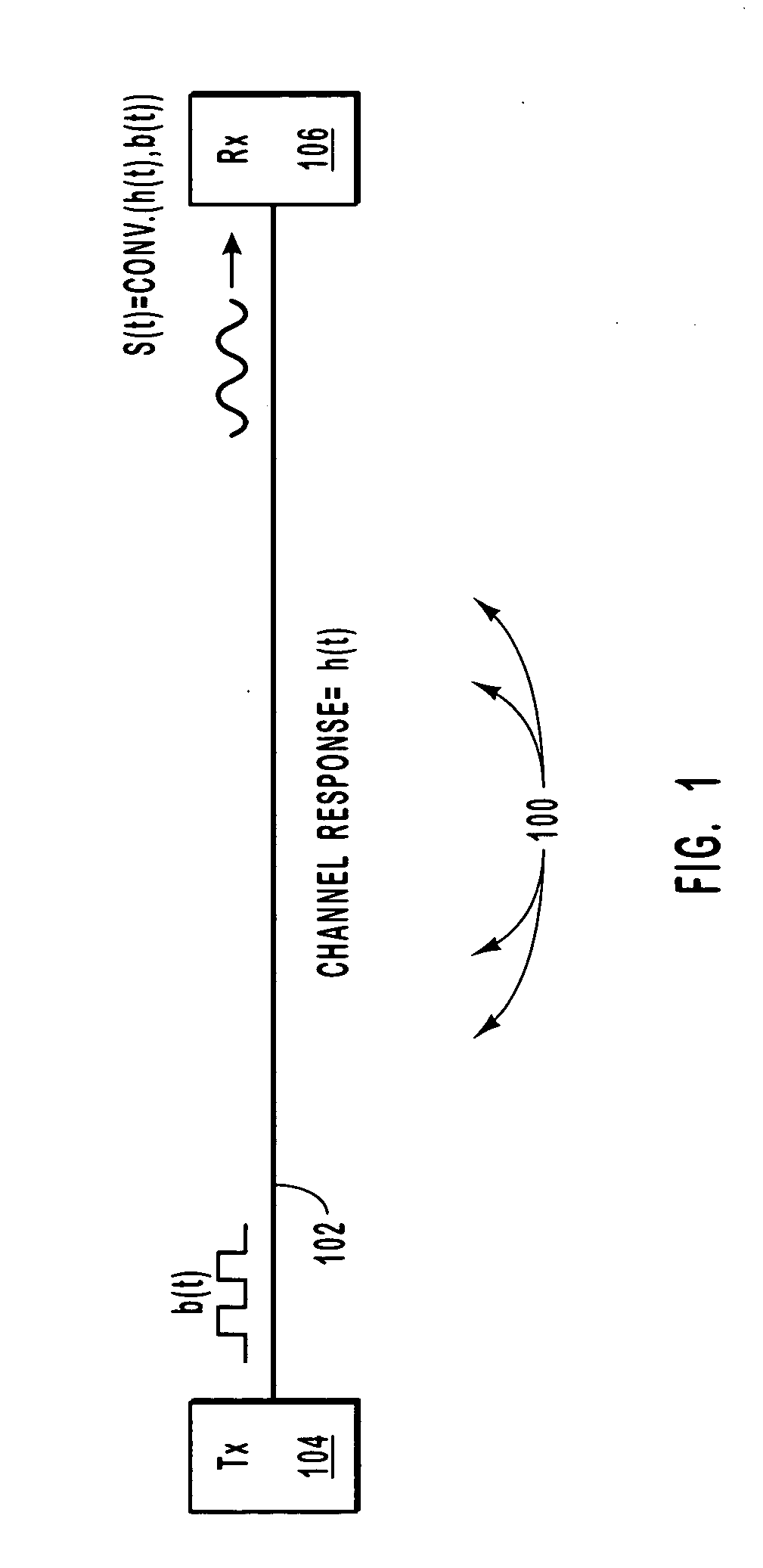
An example of optical signal dispersion is shown in FIG. 1 which generally shows a fiber-optic communication path 100. A data signal b(t) is propagated onto a fiber-optic cable 102 by a transmitter 104. When the data signal b(t) is propagated onto the fiber-optic cable 102, the transitions between high and low logical bits are sharp. As the data signal b(t) travels along the fiber-optic cable ...


PUM


Abstract

Mitigating errors caused by the dispersion of optical or electrical signals. Errors caused by dispersion in high frequency system are mitigated by passing a received signal through an adjustable linear filter that counteracts a channel response of a channel on which the received signal has traveled to produce an electrical signal. The adjustable linear filter has a number of coefficients. A figure of merit is calculated for the electrical signal, where the figure of merit includes the second and fourth moments of the electrical signal. The coefficients of the linear filter are adjusted based on the value of the figure of merit so as to minimize the figure of merit.

Description

BACKGROUND OF THE INVENTION 1. The Field of the Invention The invention generally relates to the transmission of signals in communication systems. More specifically, the invention relates to systems and methods of mitigating the effects of dispersion in high frequency communication systems. 2. Description of the Related Art In the field of data transmission, one method of efficiently transporting data is through the use of fiber-optics. Digital data is propagated through a fiber-optic cable using light emitting diodes or lasers. To send data on a fiber-optic cable, the data is typically converted from electronic data generated by computers to optical data that can be propagated onto the fiber-optic cable. This conversion is generally done using a laser or light emitting diode. When light is generated (or is at “high power”) a logical “1” is presented. The absence of light (or light at “low power”) represents a logical “0”. Thus an optical signal with sharp rising transitions and...

Claims


Application Information

Patent Timeline
IPC IPC(8): G02BH04B1/10H04B10/18H04B10/2581
CPCH04B10/2581H04B10/25133
Inventor LENOSKY, THOMAS
Owner II VI DELAWARE INC
Why Eureka
Try Eureka