Hearing aid system

Inactive Publication Date: 2005-04-14
VIVATONE HEARING SYST
View PDF62 Cites 37 Cited by
  • Summary
  • Abstract
  • Description
  • Claims
  • Application Information

AI Technical Summary

Benefits of technology

[0012] In another exemplary embodiment, the stiffening wire is provided within or on a portion of the intermediate connecting portion and extends within or on at least a portion of the receiver. In such embodiment, the receiver is positioned on the intermediate connecting portion with greater stability and resiliency. Also where a stiffening element is used, the intermediate connecting portion and receiver may be custom manufactured or custom molded to optimize positioning of the receiver within the ear canal and/or to optimize positioning of the inte

Problems solved by technology

Insertion of hearing aid receivers in the ear produces an insertion loss, which reflects a distortion or elimination of the patient's natural or original concha and ear canal resonant characteristics.
In most cases, whether the hearing aid i

Method used


Image

  • Hearing aid system
  • Hearing aid system
  • Hearing aid system

Examples


Example

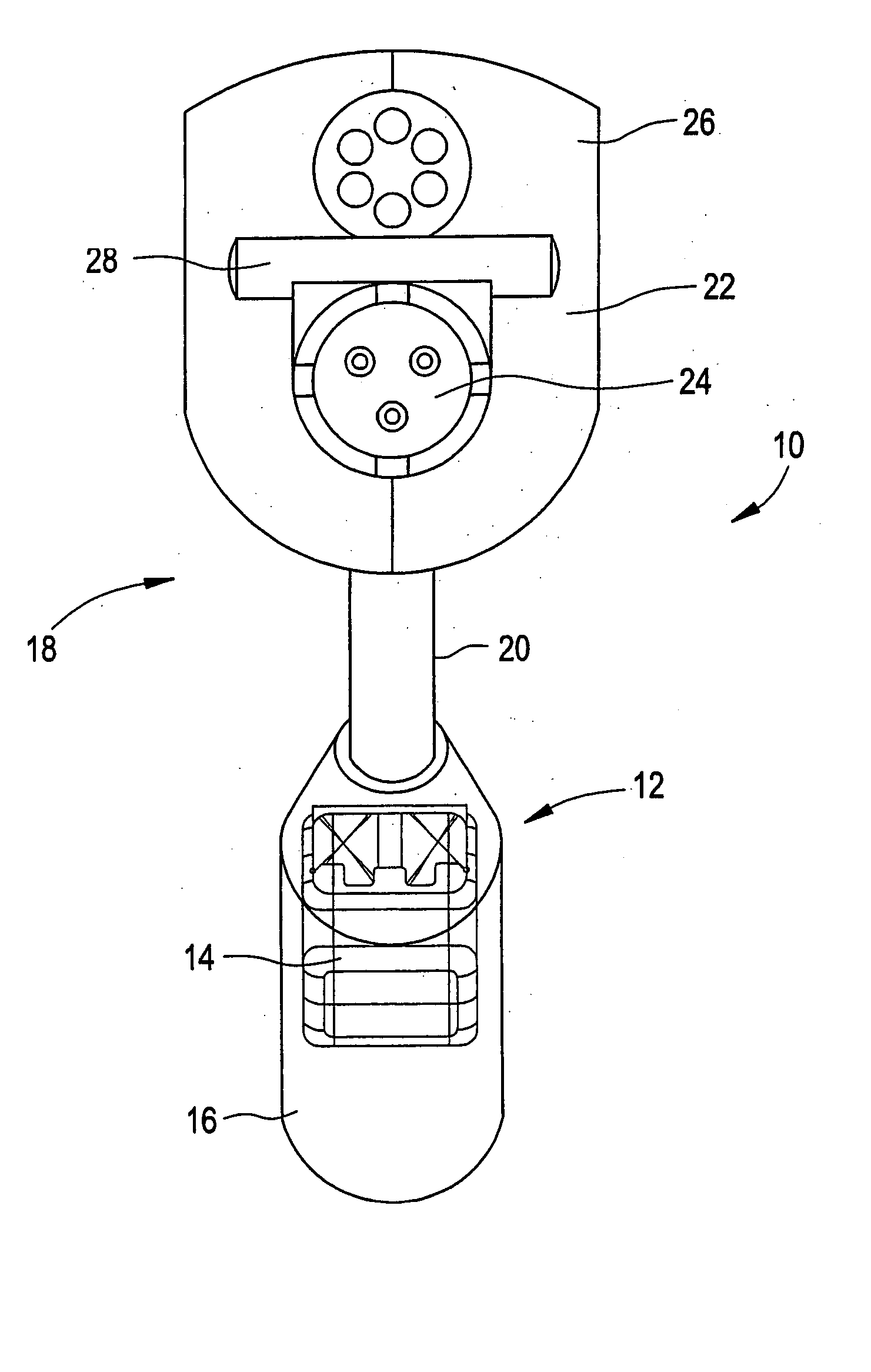
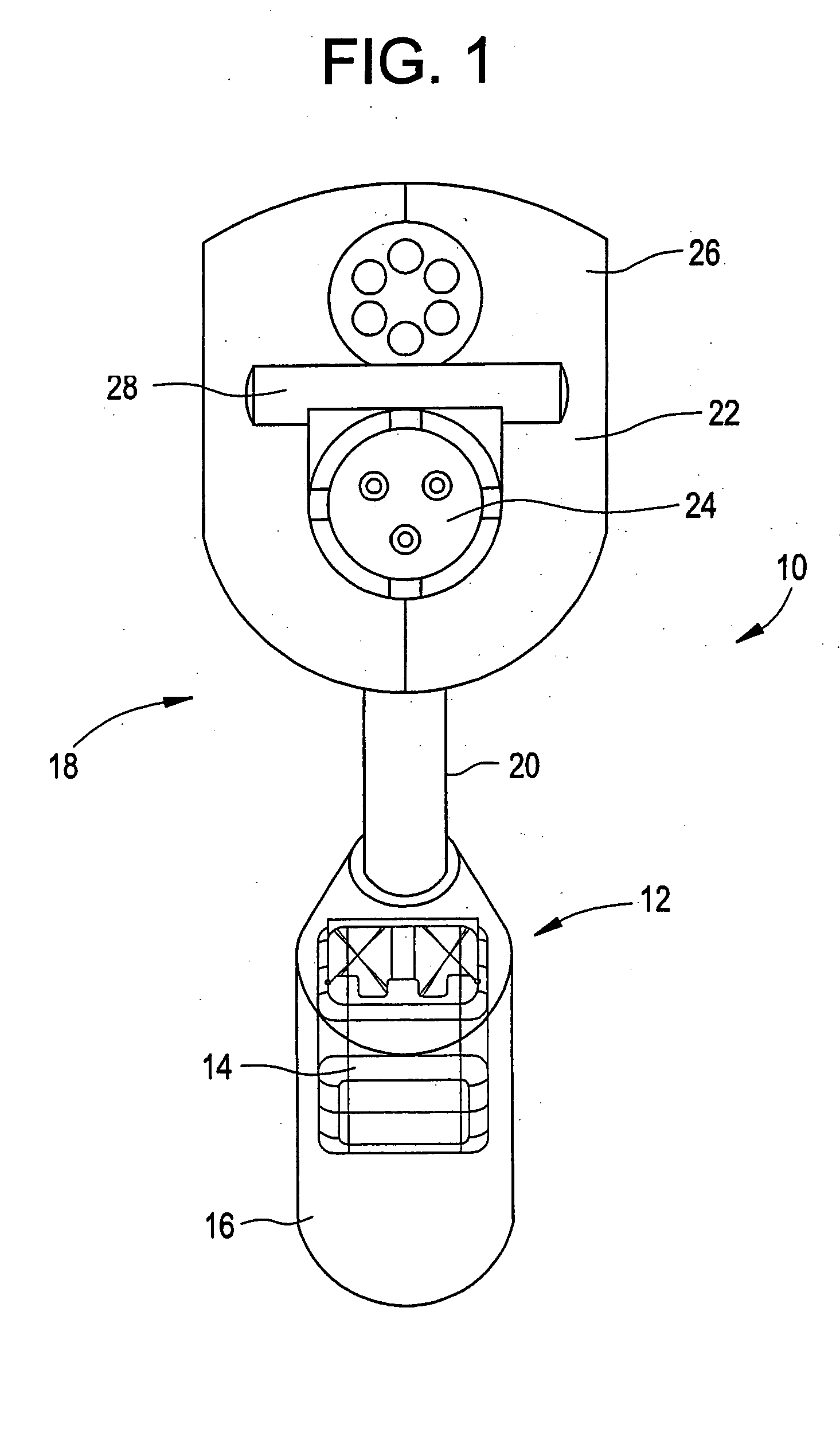
[0025] Referring now to FIG. 1, an exemplary receiver and connection portion is illustrated generally at 10 for the presently described hearing aid system. In one exemplary embodiment, the hearing aid system is configured as a completely open canal (COC) system. With reference to FIG. 1, the illustrated exemplary receiver portion, shown generally at 12, includes a speaker 14 that is at least partially surrounded by a casing 16. The receiver portion 12 is attached to a connection portion, shown generally at 18, which includes an intermediate connecting portion 20 and a sound processing component connector 22. The sound processing unit connector 22 includes an electrical interface 24 configured to mate with a corresponding electrical interface (not illustrated) on the sound processing unit. The illustrated electrical interface 24 is a three-pin female interface, surrounded by a connector shell 26. While shell 26 is illustrated as a two part shell joined by lock pin 28, it should be re...


PUM


Abstract

An exemplary hearing aid system includes a receiver configured so as to create an insertion loss over the audible range of hearing below about three decibels as compared to the unaided ear. An exemplary hearing aid system also includes one or more of: a micro-receiver positioned in an open-ear configuration within the ear canal of a user; an intermediate connecting portion extending between a sound processing unit and a receiver, wherein the intermediate connecting portion includes a stiffening wire provided on at least a portion of the intermediate connecting portion and/or within or on at least a portion of the receiver; a retaining wire extending from one of the stiffening wire and the receiver, the retaining wire configured to position within a portion of the concha of the ear; an electrical conducting component comprising two wires within distinct channels or otherwise isolated from one another within the intermediate connecting portion; and a speaker, at least partially enclosed within a casing having first and second end portions, the first end portion communicating with, the connection, the speaker communicating with a port provided at the second end portion of the casing, wherein the casing is sealed to fluids and wherein the port is sealed to fluids by a membrane or mesh material. The described hearing aid reduces the insertion and occlusion effects relative to comparison devices.

Description

CROSS REFERENCE TO RELATED APPLICATIONS [0001] The present application claims priority to U.S. Provisional Patent Application No. 60 / 445,034, filed Feb. 5, 2003, U.S. Provisional Patent Application No. 60 / 514,994, filed Oct. 27, 2003, and U.S. Provisional Patent Application No. 60 / 535,569, filed Jan. 9, 2004, the entire contents of which are specifically incorporated herein by reference.BACKGROUND [0002] A wide variety of hearing aid units are known in the art. Insertion of hearing aid receivers in the ear produces an insertion loss, which reflects a distortion or elimination of the patient's natural or original concha and ear canal resonant characteristics. The presently described hearing aid is configured to eliminate or significantly reduce such insertion losses. [0003] In some hearing aids, the receiver is also positioned within the ear canal in such a way that it creates an occlusion effect. In most cases, whether the hearing aid is fitted in the ear, as with a custom made inst...

Claims


Application Information

Patent Timeline
IPC IPC(8): H04R25/00
CPCH04R25/60H04R25/604H04R25/658H04R2460/09H04R25/652H04R25/603H04R25/609H04R2225/57
Inventor BAUMAN, NATAN
Owner VIVATONE HEARING SYST
Why Eureka
Try Eureka