Shaft for fluid dynamic bearing, fluid dynamic bearing device, and method of manufacturing the shaft

Inactive Publication Date: 2005-04-14
NHK SPRING CO LTD
View PDF8 Cites 12 Cited by
  • Summary
  • Abstract
  • Description
  • Claims
  • Application Information

AI Technical Summary

Benefits of technology

It is an object of the present invention to provide a shaft for a fluid dynamic bearing, which has the rotation stability to control a half whirl and decrease the rotation frequency at start of contact between

Problems solved by technology

In these machining processes, it is difficult to increase the machining accuracy above than a certain level.
Formation of a separation layer may caus

Method used


Image

  • Shaft for fluid dynamic bearing, fluid dynamic bearing device, and method of manufacturing the shaft
  • Shaft for fluid dynamic bearing, fluid dynamic bearing device, and method of manufacturing the shaft
  • Shaft for fluid dynamic bearing, fluid dynamic bearing device, and method of manufacturing the shaft

Examples


Embodiment Construction

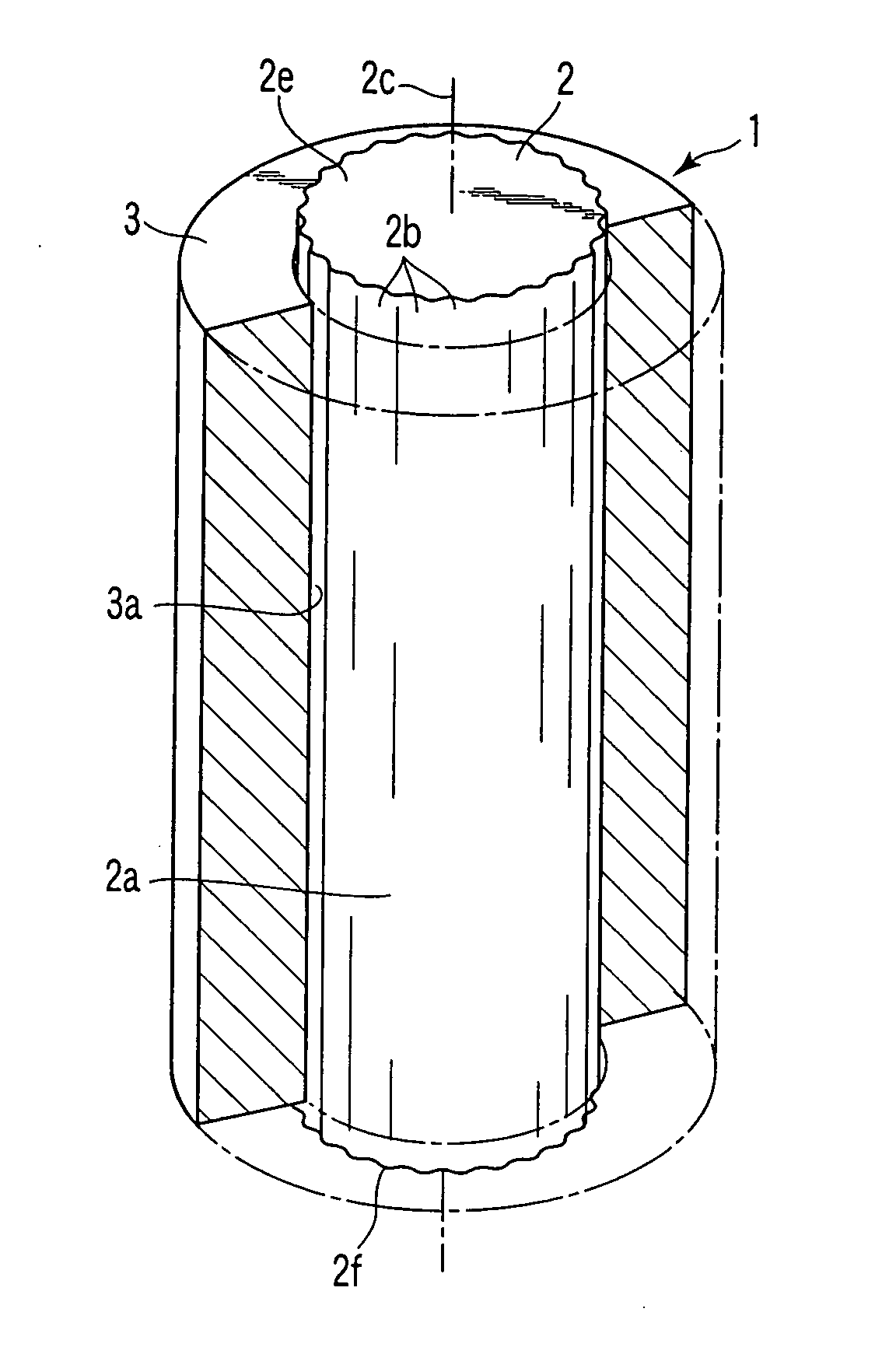
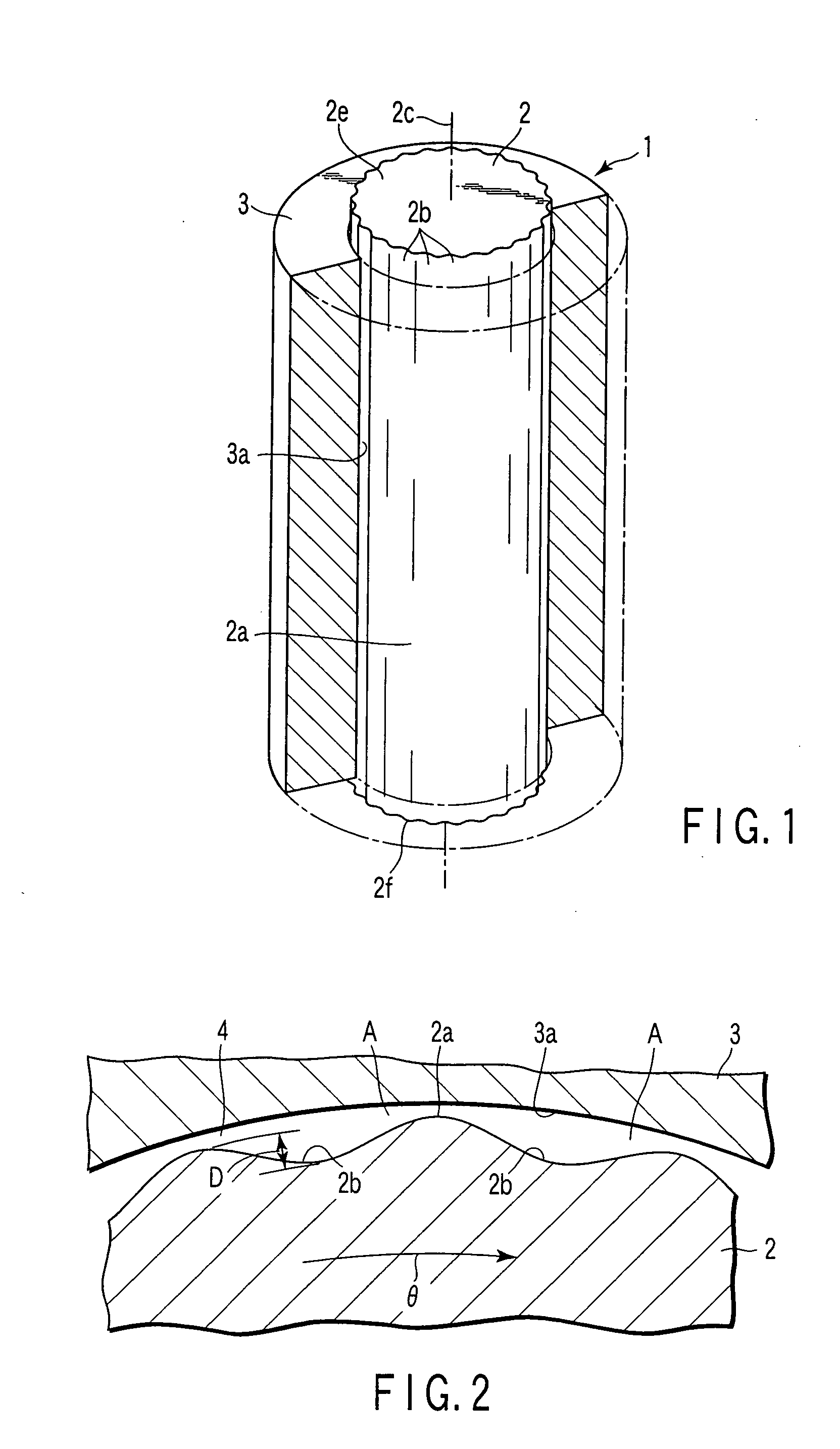
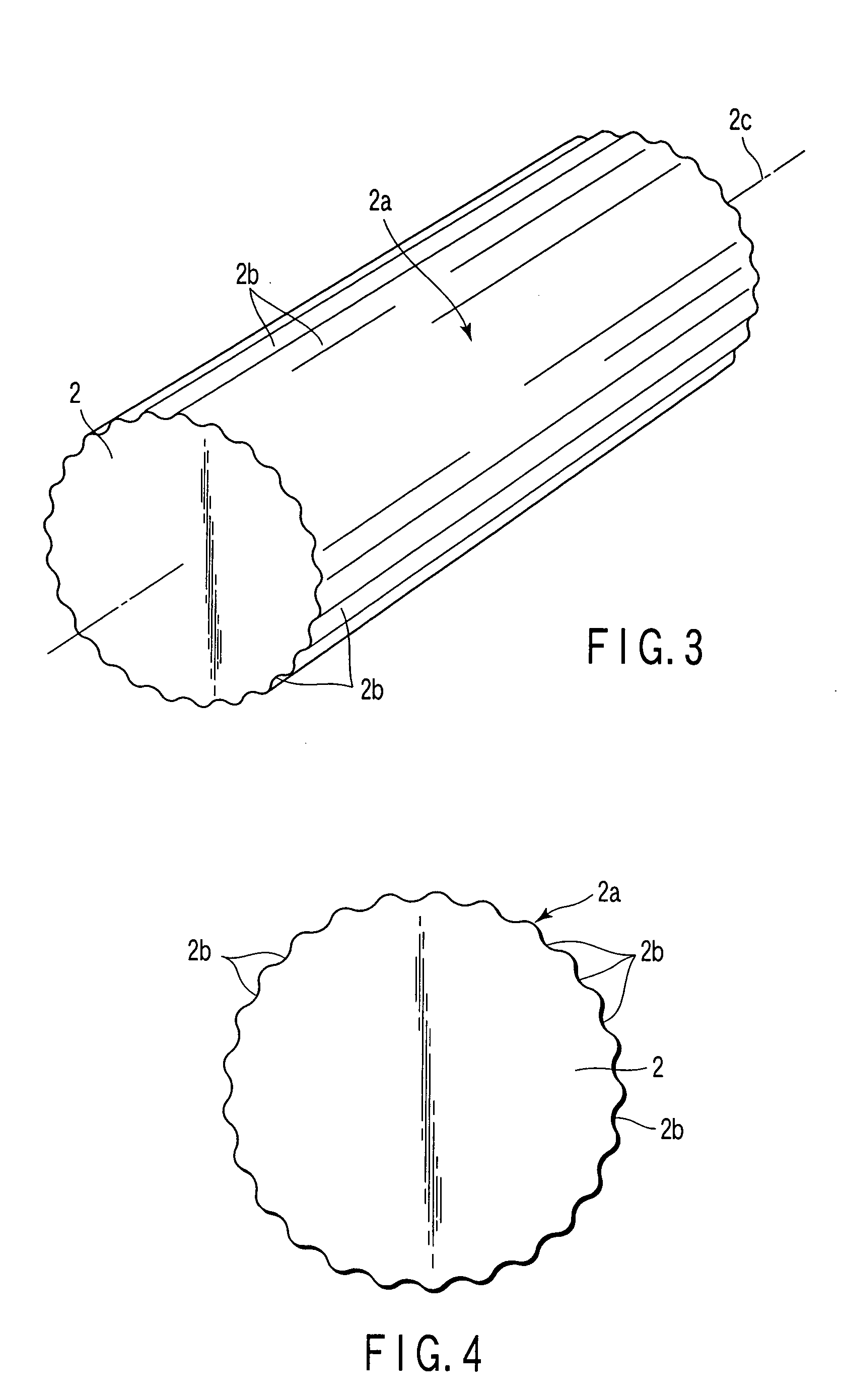
A fluid dynamic bearing device 1 according to a first embodiment of the present invention will be explained hereinafter with reference to the accompanying drawings FIG. 1 to FIG. 8. As shown in FIG. 1, a fluid dynamic bearing device 1 has a shaft 2 and a bearing 3. The shaft 2 is formed with a plurality of grooves 2b (25 grooves in FIG. 1 to FIG. 4) in an external circumference 2a. In this embodiment, the depth D of the grooves 2b is shown larger than the actual depth to clarify the grooves. For example, when the diameter (maximum) of the shaft 2 is about 10 mm in the fluid dynamic bearing device 1 using air as a fluid, the depth D of the grooves 2b shown in FIG. 2 is about several micrometers.

The depth D of the grooves 2b is preferably set larger proportional to the diameter of the shaft 2. According to the principle of generating a fluid dynamic, the depth D of the grooves 2b is set to a range of 1-100 μm, not proportional to the shaft diameter, but depending on the rotation freq...


PUM

PropertyMeasurementUnit
Lengthaaaaaaaaaa
Diameteraaaaaaaaaa
Depthaaaaaaaaaa

Abstract

In a method of manufacturing a shaft for the fluid dynamic bearing device, the shaft is formed with a plurality of grooves arranged in and around the external circumference, the surface of the grooves and external circumference with uniform roughness, and machined marks on the surface aligned in the circumferential direction, by controlling the relative vibration of a rod-shaped blank to be machined as the shaft for a fluid dynamic bearing and a grinding wheel (a machining tool) to grind the external circumference of the blank.

Description

BACKGROUND OF THE INVENTION 1. Field of the Invention The present invention relates to a shaft for a fluid dynamic bearing device, which has an external circumference shaped to generate a fluid dynamic in a clearance to a bearing when rotated relatively to the bearing, a fluid dynamic bearing device having the shaft, and a method of manufacturing the shaft. 2. Description of the Related Art In a certain type of fluid dynamic bearing, grooves are formed in the direction across the sliding direction in at least one of a bearing surface of a shaft and a bearing, to improve the stability of the axis of rotation. The grooves are available in two types, the herringbone type (e.g., Jpn. Pat. Appln. KOKAI Publication No. 2000-227119), and the type arranged parallel to the axis of rotation (e.g., International Pat. Appln. KOKAI Publication No. 98 / 38433). Another type of dynamic air pressure bearing device has a fixed shaft, and a hollow rotation shaft fit with clearance to the external ...

Claims


Application Information

Patent Timeline
IPC IPC(8): B24B5/22B24B19/02F16C3/02F16C17/02F16C33/10F16C33/14
CPCB24B5/22B24B19/028F16C3/02F16C17/028F16C33/1065F16C33/14F16C17/026F16C2223/42F16C2220/70F16C2220/60F16C17/02F16C33/20
Inventor FURUTA, EIJIROKAYAMA, KENJIMASUDA, MICHIYA
Owner NHK SPRING CO LTD
Why Eureka
Try Eureka