
Container forming machine

Inactive Publication Date: 2005-04-14
JOHN FLUKE MFG CO INC
View PDF3 Cites 37 Cited by
  • Summary
  • Abstract
  • Description
  • Claims
  • Application Information

AI Technical Summary

Benefits of technology

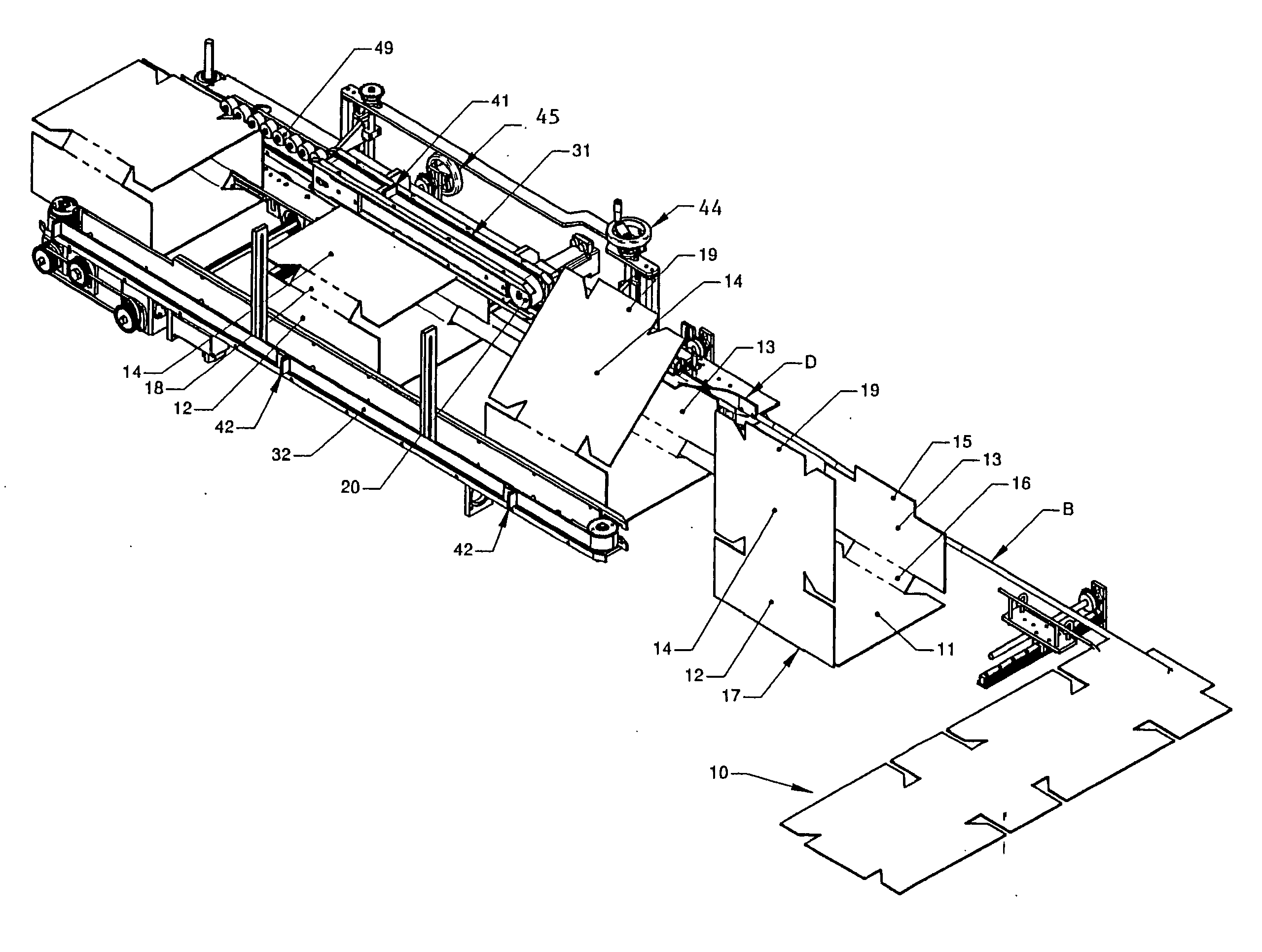
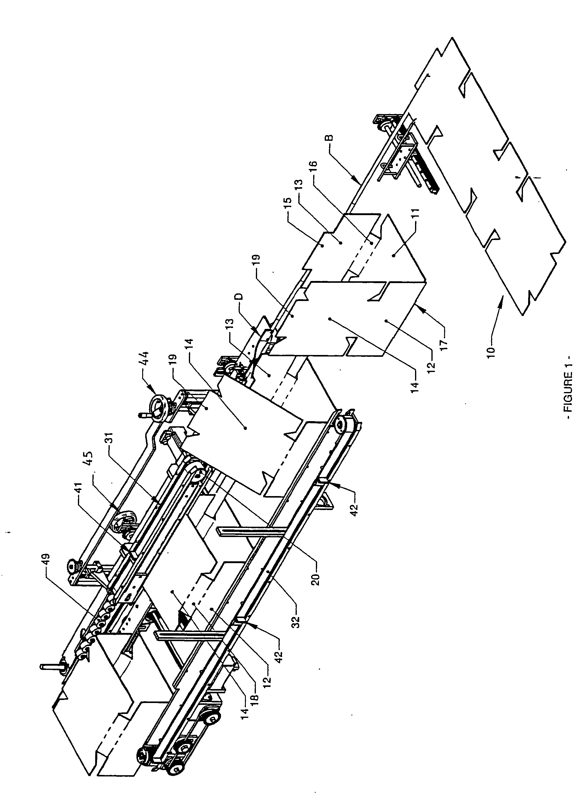
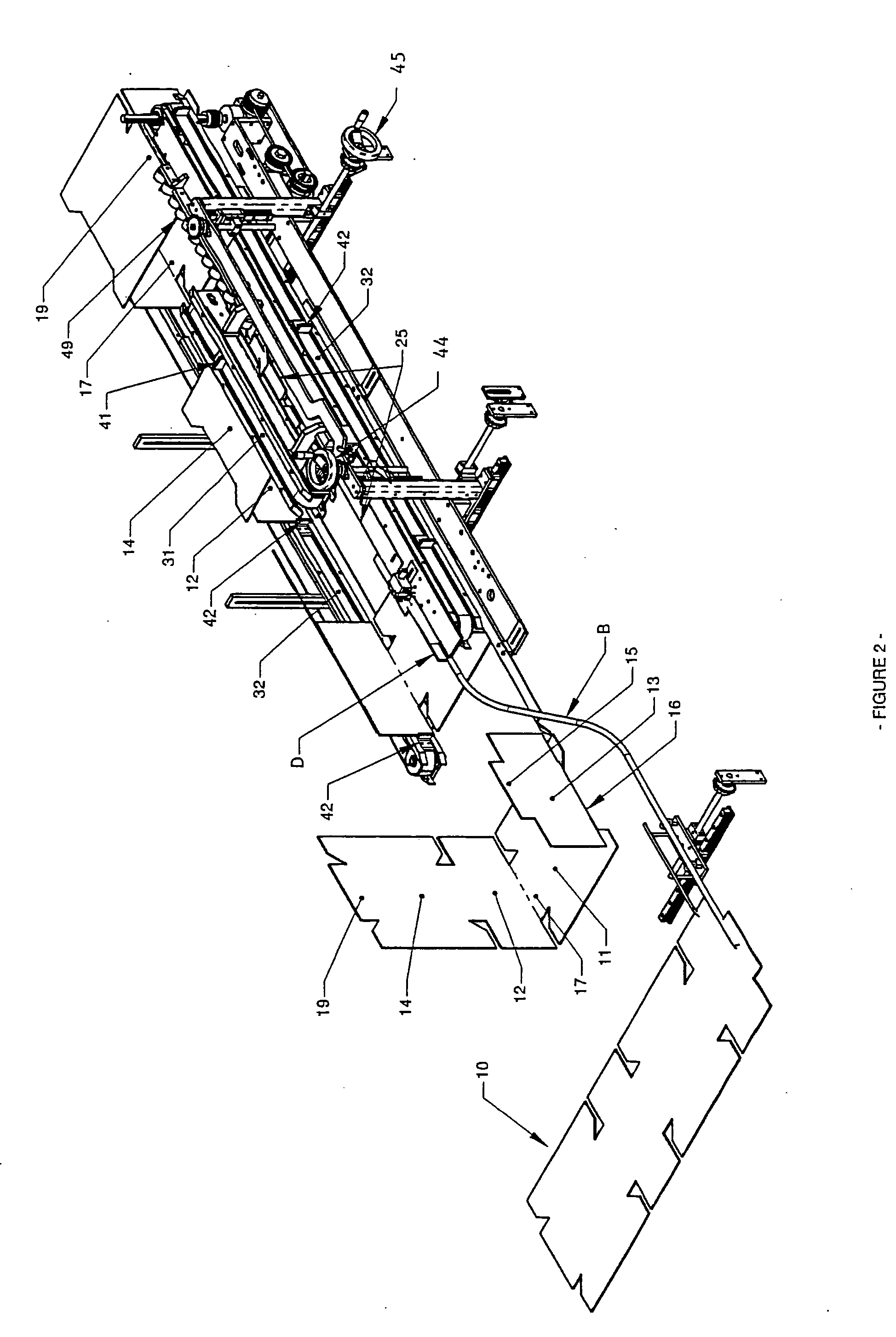
[0023] The present invention is a space efficient container-forming machine having an optional pre-formation dunnage removal and staging section, an apparatus for forming the bodies of multi-sided containers from flat single-sheet paperboard blanks that assures proper alignment of the leading and trailing edges of the container blank before adhering the first and last body panels of the blank together, an apparatus for altering the path of the partially-formed container bodies while rotating the bodies themselves to a selected angle or position, and a final formation section where the bottom panels of the container are folded and adhered together. In a preferred embodiment, the alignment apparatus is located above the dunnage removal and staging section, and path of container formation inside the machine doubles back against itself in a U-turn (180 degrees), thereby reducing the overall footprint of the machine. During the U-turn, the partially-formed container is positioned for further formation activity by rotating the container itself only 90 degrees. The machine is generally designed for use with containers having more than fours sides, but may be adapted for use in forming 4-sided as well as RSC containers.

Problems solved by technology

This is because the friction between the panels of the blank and the various plows and guides may cause some of the panels to lag behind others.

Method used


Image

  • Container forming machine
  • Container forming machine
  • Container forming machine

Examples


Embodiment Construction

[0061] Referring to the drawings wherein like reference characters designate like or corresponding parts throughout the several views, and referring particularly to FIGS. 11 and 13-14, it is seen that the first optional section of the machine is an apparatus for removal of a lower dunnage sheet 81 from the bottom of a stack of container blanks 10. A set of upper rollers 86 are attached to a rotatable bar 85. A set of corresponding lower rollers 88 (not shown) are provided below rollers 86 for engagement therewith. Rollers 86 and 88 are provided with teeth, grippers or other frictional surfaces for engaging dunnage sheets 81. Operation of a lever 83 imparts rotation to bar 85 pulling rollers 86 away from lower rollers 88. Dunnage sheet 81 is then inserted between rollers 86 and 88 as shown in FIG. 11. The operation of lever 83 is then reversed causing rollers 86 to close against dunnage sheet 81, pinching sheet 81 between rollers 86 and 88, and bending the leading edge of sheet 81 do...


PUM


Abstract

The present invention is a space efficient container-forming machine having an optioinal pre-formation dunnage removal and staging section, an apparatus for forming the bodies of multi-sided containers from flat single-sheet paperboard blanks that assures proper alignment of the leading and trailing edges of the container blank before adhering the first and last body panels of the blank together, an apparatus for altering the path of the partially-formed container bodies while rotating the bodies themselves to a selected angle or position, and a final formation section where the bottom panels of the container are folded and adhered together. In a preferred embodiment, the alignment apparatus is located above the dunnage removal and staging section, and path of container formation inside the machine doubles back against itself in a U-turn (180 degrees), thereby reducing the overall footprint of the machine. During the U-turn, the partially-formed container is positioned for further formation activity by rotating the container itself only 90 degrees. The machine is generally designed for use with containers having more than fours sides, but may be adapted for use in forming 4-sided as well as RSC containers.

Description

BACKGROUND OF THE INVENTION [0001] 1. Field of the Invention [0002] The present invention relates to machines and methods for forming containers from flat paperboard blanks, and more particularly to machines and methods for forming multi-sided containers in an optimal dimensional profile. [0003] 2. Description of the Prior Art [0004] In the packaging industry, it has been found most efficient and otherwise effective to employ paperboard containers (“boxes” or “cases”) for the packing, shipment and storage of commodities such as fresh fruit, fresh vegetables and meat, pre-packaged goods (e.g. cans of soup, bottles of beverages, jars of jelly, bags of rice, cartons of cereal, etc. (“cartons”)) as well as a wide assortment of other products. Paperboard containers are comparatively inexpensive, light in weight, sufficiently strong for the prescribed usage and disposable at the ultimate destination. [0005] Numerous paperboard containers and designs have been developed over the years alon...

Claims


Application Information

Patent Timeline
IPC IPC(8): B31B3/00B31B3/36B31B3/64B31B11/00B31B50/42B31B50/62B65D5/02B65D5/42B65G47/244B65G47/84
CPCB31B1/36B31B1/42B31B1/62B31B3/00B65G47/843B31B2201/265B65D5/02B65D5/4204B65G47/244B31B2201/2637B31B50/36B31B50/42
Inventor MOSHIER, JAMESDJOKOVIC, DANNOURIAN, DAN
Owner JOHN FLUKE MFG CO INC
Learn More