Cutting stent

a stent and stent technology, applied in the field of stents, can solve problems such as complications and more serious problems, and achieve the effects of reducing the multi-step process, less steps, and safer and better procedures

Active Publication Date: 2005-04-14
BARONGAN MARK GELIDO
View PDF15 Cites 106 Cited by
  • Summary
  • Abstract
  • Description
  • Claims
  • Application Information

AI Technical Summary

Benefits of technology

[0013] The new stent will reduce the multi-steps process that requires the exchange of a cutting balloon in order to place the stent in blockage area to direct placement of stent in the area. The general knowledge and acceptance with intravascular procedures is that, the less the steps, the safer and better the procedure will be. Multi-steps processes can elevate the complication and chances of scratching of intimal wall, cuts, punctures, falling debris, and the like, which ultimately can lead to more serious problems and complications. Therefore, the new stent will reduce the likelihood of small and larger plaque and debris that can be dislodged in the distal blood vessel causing flow obstruction.
[0014] The new stent will also reduce the likelihood of falling debris in blood stream that is caused by scoring of the hard plaque and debris. The current cutting balloon has blades that have square sides. The new stent will have an angular or beveled face at the beginning and end of each blade. The angular raise will facilitate the ease of the blades into to plague and debris. With fewer disturbances in the area, the likelihood of falling debris from the plague will also greatly lessen.
[0015] The other cause of falling debris in blood stream is the multiple contacts of the intravascular procedural equipments. The new stent eliminates the need to change equipment in and out of a blood vessel like the changing of equipment if a cutting balloon were used. The new stent's blades will serve the function as the cutting balloon.
[0016] Moreover, the new stent will reduce the likelihood of practitioners cutting into artery causing an intimal flap in the artery caused by over-inflation of the current cutting balloon. Using the current cutting balloon causes micro tears on the intimal wall of a blood vessel. With the new stent, the bars or blades cut while the stent body is tacking up any micro-tears and falling debris. Additionally, the chances of over-inflating, causing a serious score through the blood vessel are eliminated because the new stents has a stent pattern integrating the blades.

Problems solved by technology

Multi-steps processes can elevate the complication and chances of scratching of intimal wall, cuts, punctures, falling debris, and the like, which ultimately can lead to more serious problems and complications.
The other cause of falling debris in blood stream is the multiple contacts of the intravascular procedural equipments.

Method used


Image

  • Cutting stent
  • Cutting stent
  • Cutting stent

Examples


Embodiment Construction

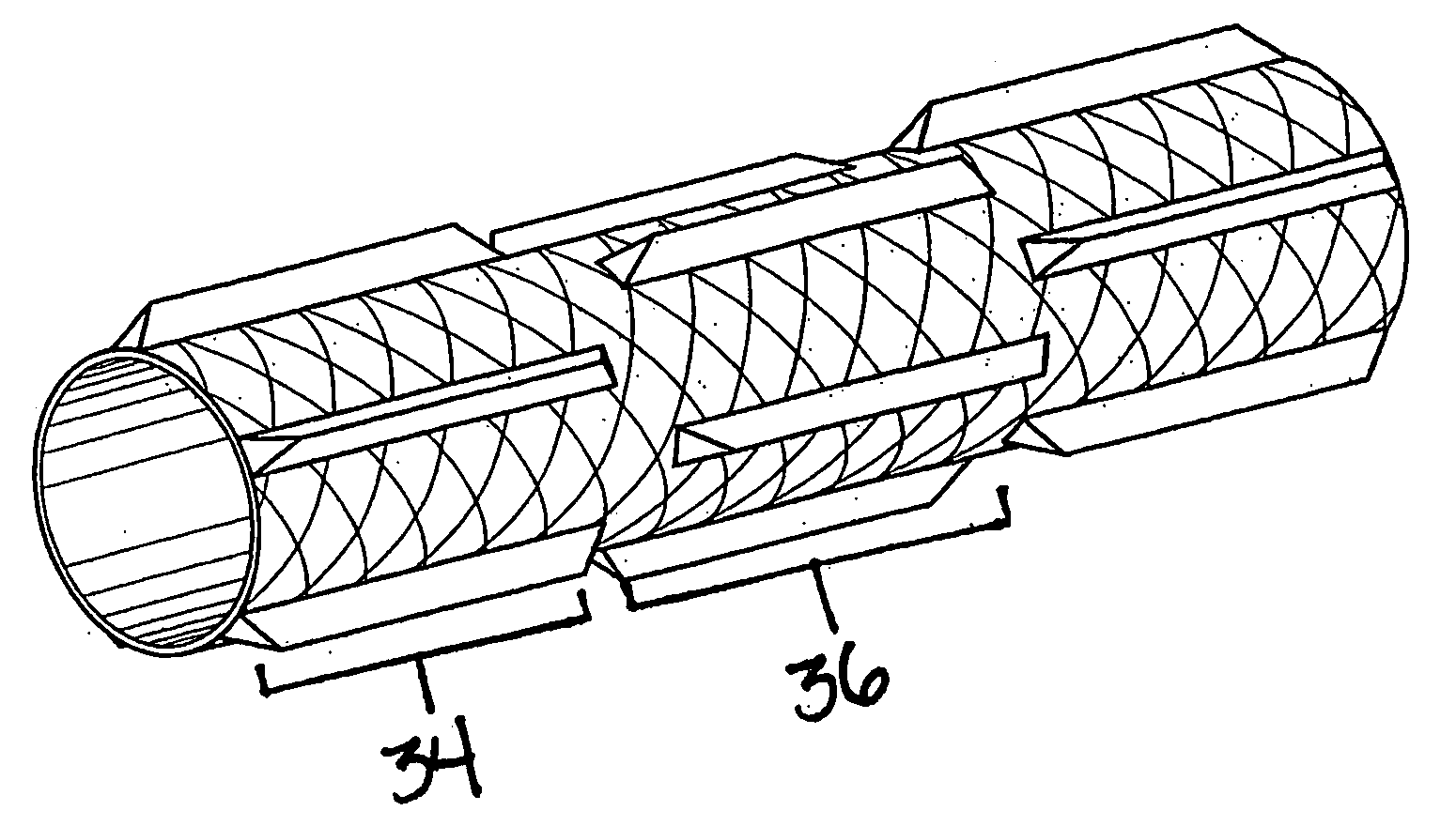
[0037] The flat view FIG. 18 consists of the blades integrated with a strut pattern. The strut pattern 40 integrates to the sides of each blade. Each strut 44 has an open ring with an edge, where each edge has an arm extending from the opening edge of the circle. At the end of each arm, another open-end circle joins. The pattern of open-ended circles and arms replicate to form an expandable, flexible pattern that integrates each blade 26. Each subsequent set of staggered blades 36 connects to the previous set of staggered blades 34 by each arm that extends from each open-ended circle to the base of each end of the blade surface 42. At the point of attachment 42, the two arms connect to the base of each blade's beveled edge 46.

[0038] The stent's material is composed of any conventional metals used in conventional stents. The strut design of stent is to the discretion of individual manufactures. However a pattern shown FIG. 18 integrates the blades in a stent pattern. The main embodi...


PUM


Abstract

This invention is a stent that has cutting bars or blades in the direction of the balloon and longitudinally at five equidistant points along the direction of the stent's body. There are two patterns in this invention. The first pattern has five blades equidistant from the other and run longitudinally along the direction of the stent body and the other pattern has five shorter blades equidistant from the other to constitute one set. Each set is arranged in a staggered pattern from the next set. Furthermore, the edges of stent's blades or bars are angular or beveled and integrated into a stent strut pattern in order to facilitate the entry of blades into a blockage caused by calcium, plague and/or debris.

Description

CROSS-REFERENCE TO RELATED APPLICATIONS [0001] This application claims priority to Provisional Application No. 60 / 510,114 filed Oct. 10, 2003.FEDERALLY SPONSORED RESEARCH [0002] Not Applicable TECHNICAL FIELD OF INVENTION [0003] This invention is a stent for intravascular procedures that replaces the application of a cutting balloon in order to facilitate the placement of the stent in a blood vessel blockage. BACKGROUND OF INVENTION [0004] Intravascular stents are commonly used to maintain patency, opening or spread, of a blood vessel in an attempt to maintain normal blood flow in situation such as stenosis, a constriction of blood vessels due to plague, calcium, thrombus, and other debris or combination of these. Intravascular stents are typically metallic and self-expanding or balloon expandable. However, cases where the blockage, which is composed of plague, calcium, and other calculus debris, is severe, cutting into the blockage is required in order to enable the delivery and pl...

Claims


Application Information

Patent Timeline
Patent Type & Authority Applications(United States)
IPC IPC(8): A61B17/00A61B17/22A61F2/02A61F2/86
CPCA61F2/86A61B17/320725A61B17/320758A61B2017/00353A61F2/07A61F2/848A61F2220/0016A61F2230/005
Inventor BARONGAN, MARK
Owner BARONGAN MARK GELIDO
Why Eureka
Try Eureka