RTK positioning system and positioning method therefor

a positioning system and positioning method technology, applied in direction finders using radio waves, navigation instruments, instruments, etc., can solve the problems of inability to receive signals, erratic or impossible reception of satellite signals, and repeated operation of ambiguity determination operations, so as to reduce the number of devices to be installed indoors

Active Publication Date: 2005-04-14
GNSS TECH INC
View PDF6 Cites 20 Cited by
  • Summary
  • Abstract
  • Description
  • Claims
  • Application Information

AI Technical Summary

Benefits of technology

[0020] Therefore, the positioning that employs the carrier phase can be performed even in places, such as indoors, where a GPS signal cannot be received, or in places hidden from the satellite, such as those in mountains and forests and behind skyscrapers in cities, where the number of GPS signals required for positioning cannot be received. As a result, an accurate positioning having an error of only several mm to several cm can be performed.
[0045] Thus, the number of the devices to be installed indoors can be reduced.

Problems solved by technology

However, because of external factors, such as the affect of wave transmission delay in the ionosphere or the troposphere, or a radio environment such as a multipath at a measurement point, an interrupt or a break in the reception of a signal from a satellite is not rare, and each time the signal reception is interrupted, the ambiguity determination operation must be repeated.
A big problem that affects not only RTK positioning but, in general, all satellite dependant positioning methods that employ satellites, is that in mountains and forests and among skyscrapers, and in tunnels and buildings and underground, so-called hidden locations, as viewed from a satellite, the reception of satellite signals is erratic or impossible.
Therefore, sometimes either satellite signals cannot be received, or the number that are received is insufficient for positioning.
In such a case, either positioning cannot be performed, or it cannot be performed correctly.
Therefore, if positioning will start to perform with reference to an initial location where the positioning could not completed, no past history is available and positioning cannot be performed for that location.
Therefore, the initial location of the rover receiver of the user cannot be determined, and an accurate carrier phase positioning function having an error of only several mm to several cm cannot be employed.
However, according to the positioning method employing the carrier phase, the location of the reference receiver must be obtained before the ambiguity determination operation is begun, so that the method studied by the inventors is not a viable solution.
Further, although an independent positioning method employing code is also available, this method is not appropriate, especially for accurate positioning indoors, because an error of at least several m occurs.
The problem to be resolved is that, in places such as outdoors where a signal cannot be received from a satellite, and places geographically hidden from the satellite, such as those in cities or in mountains, where the number of signals required for positioning cannot be received from a satellite, the positioning method employing the carrier phase cannot be used, and accurate positioning is impossible.
Specifically, the problem is that when a user does not have any advance information for a location, the user has no means for determining his or her location.

Method used


Image

  • RTK positioning system and positioning method therefor
  • RTK positioning system and positioning method therefor
  • RTK positioning system and positioning method therefor

Examples


Embodiment Construction

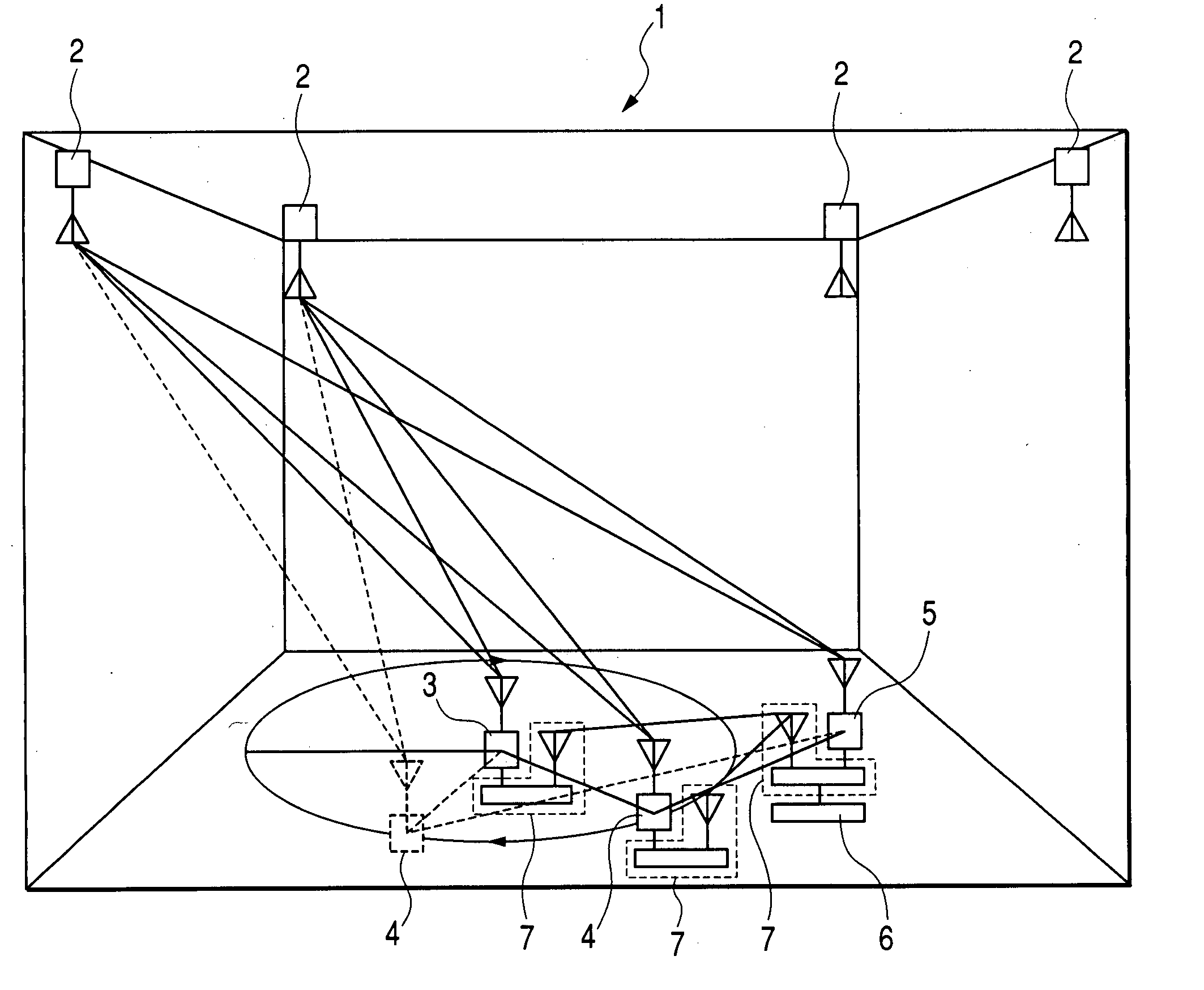
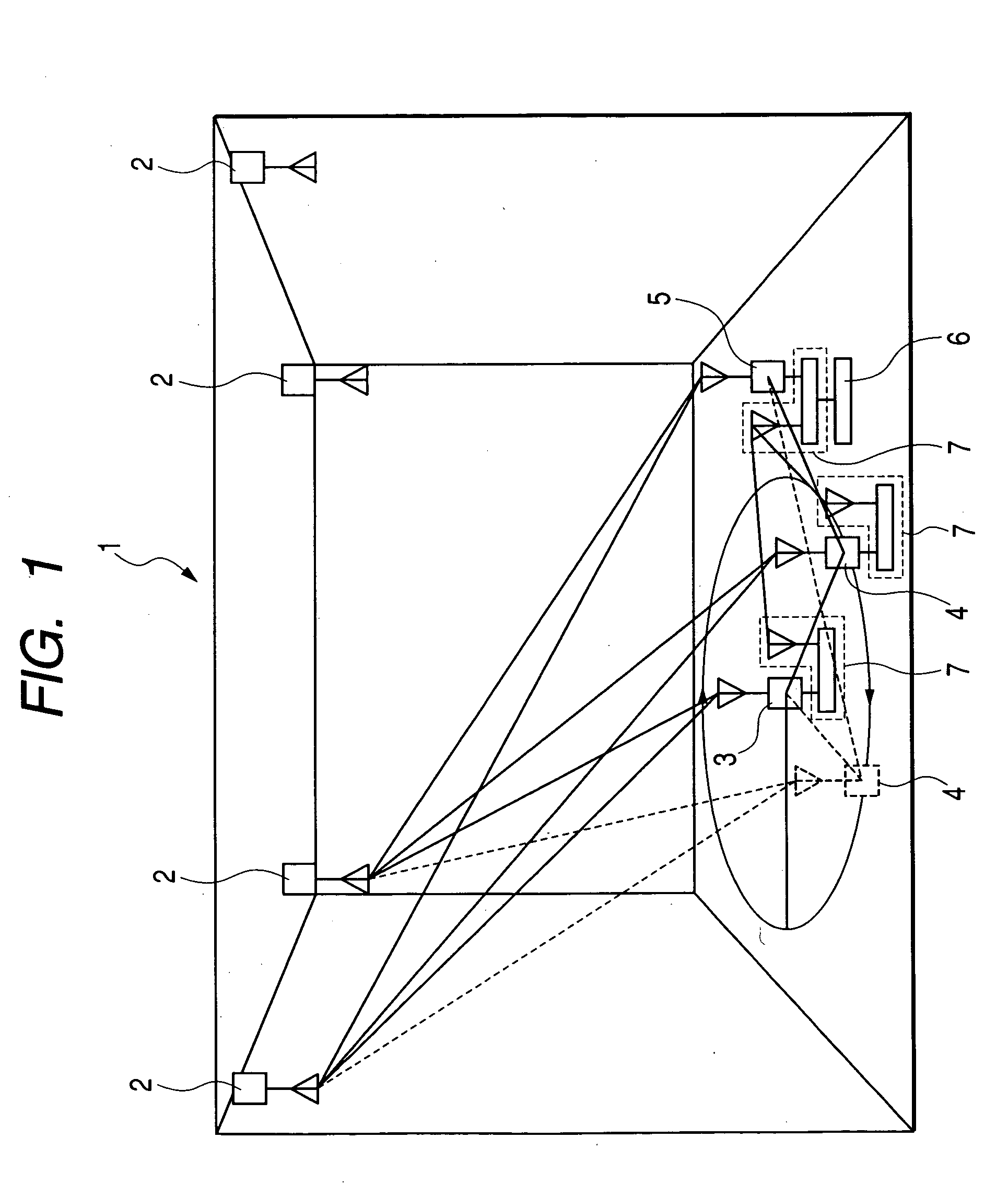
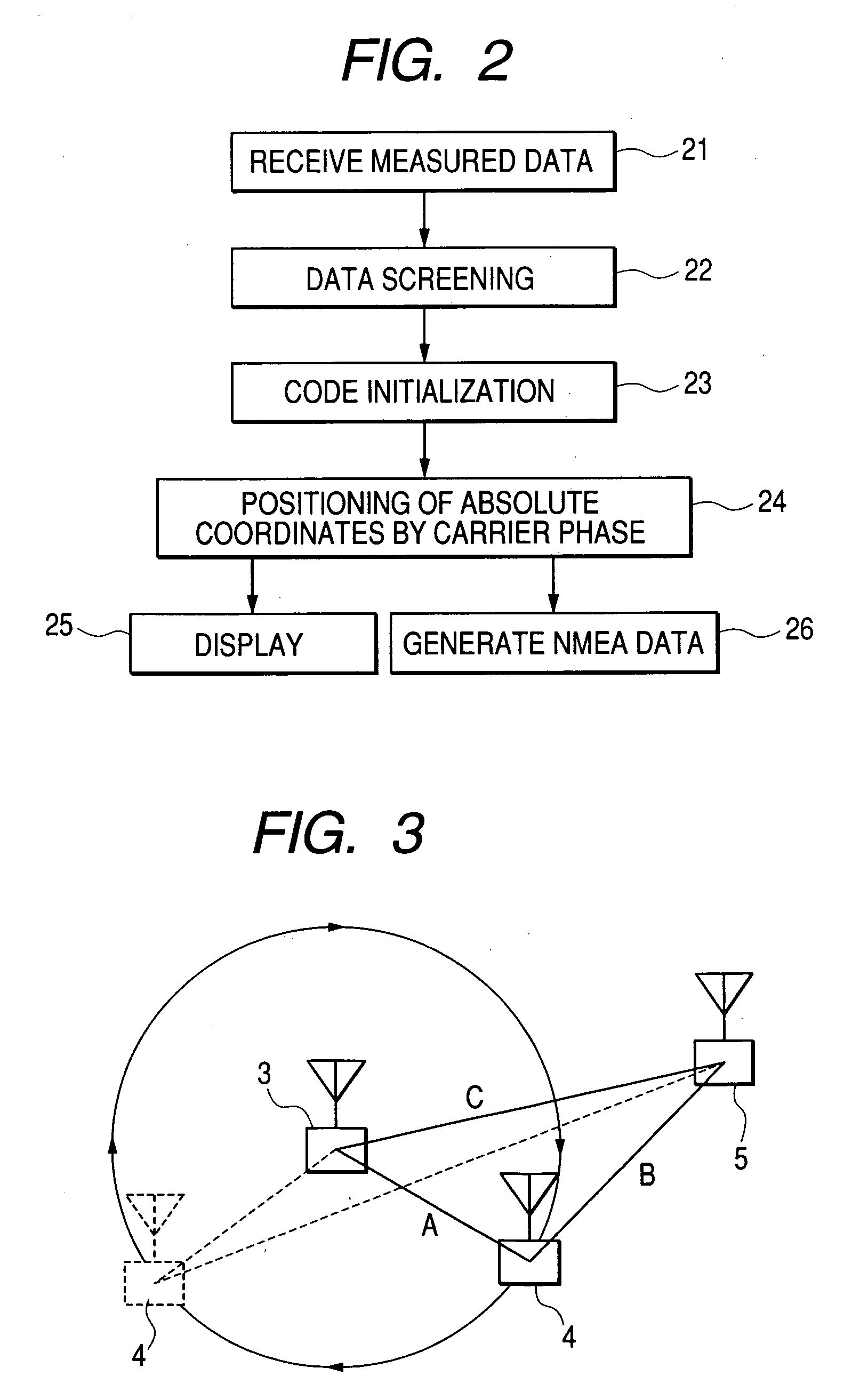
[0049] Assume that the locations of a pseudolite and a stationary reference station are previously obtained, and that code and carrier phase of a signal transmitted from the pseudolite are measured by the stationary reference station, a moving reference station and a rover receiver held by a user. Data of the code and the carrier phase, which are measured by the stationary reference station, the moving reference station and the rover receiver, are transmitted to a user processing unit using a data link. The user processing unit determines a baseline between the stationary reference station and the moving reference station and a baseline between the moving reference station and the rover receiver, and employs the two baselines and the previously known location of the stationary reference station to determine the position of the rover receiver. Therefore, even in places, such as indoors, where a GPS signal cannot be received, or in places hidden from the satellite, such as those in mo...


PUM


Abstract

The locations of pseudolites and the location of a stationary reference station are previously known by a user processing unit, and codes and carrier phase of signals transmitted from the pseudolites are measured by the stationary reference station, a moving reference station and a rover receiver. Data of the codes and the carrier phase measured by the stationary reference station, the moving reference station and the rover receiver are transmitted to the user processing unit using a data link. The user processing unit determines a baseline between the stationary reference station and the moving reference station, and a baseline between the moving reference station and the rover receiver. The two baselines and the previously known location of the stationary reference station are employed to determine the position of the rover receiver.

Description

BACKGROUND OF THE INVENTION [0001] 1. Field of the Invention [0002] The present invention relates to a real time kinematic (hereinafter referred to as RTK) positioning system and an RTK positioning method therefor, and particularly to an accurate RTK positioning system that employs a pseudolite using carrier phase. [0003] 2. Description of the Related Art [0004] Many positioning methods are available for using artificial satellites (hereinafter referred to simply as “satellites”), but currently, the most generally used positioning method is one employing a GPS satellite. Various positioning methods are also available for using the GPS; of these, a positioning method using carrier phase is superior because of its high accuracy, i.e., errors of only several mm to several cm, and the short positioning period it requires. For a positioning method that employs carrier phase, wave-number indeterminacies (hereinafter referred to as “ambiguities”) in carrier phase data must be determined, a...

Claims


Application Information

Patent Timeline
Patent Type & Authority Applications(United States)
IPC IPC(8): G01S1/00G01S5/12G01S19/11G01S19/12G01S19/44
CPCG01S19/44G01S19/11G01S5/14
Inventor PETROVSKI, IVAN G.TORIMOTO, HIDEYUKI
Owner GNSS TECH INC
Why Eureka
Try Eureka